MP3 Jukebox
About
Current Progress
Construction
Software
Photos
|
 |
|
| |
|
|
|
| |
|
During Final Assembly
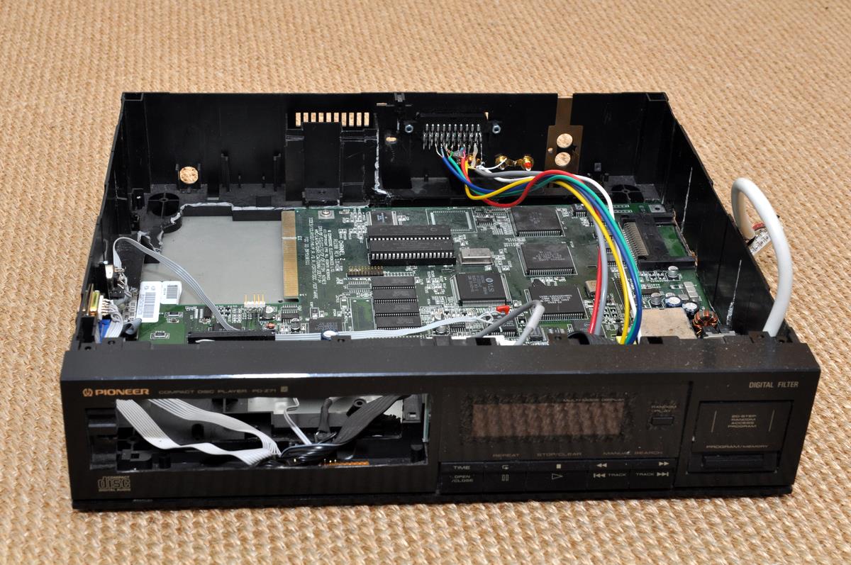
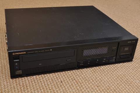
These photos were taken when I eventually got around to starting to put all the parts in the case. I knew all the parts worked outside the case, but fitting them all in is a different story! Here is the view of the shell from the front:
 View of the case View of the case
In this case the front panel is already assembled - though this simply consists
of the original buttons panel PCB and a Crystalfontz LCD display substituted in
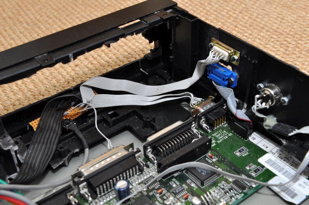
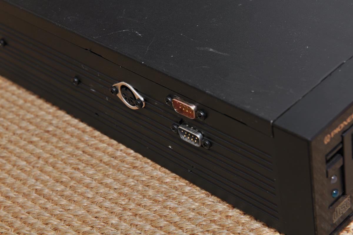
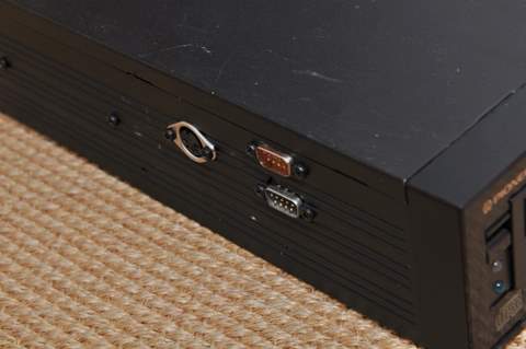
place of the original vacuum-fluorescent display. Along the way, one of the many afterthoughts had was to use the machine for some Amiga games using the excellent WHDLoad. And why not? It'll be near the TV and the sound system, just plug in two joysticks and settle in for some SWOS action! To allow this though, the ports were brought out to the side of the case as can be seen in the following photo, along with an A3000-style keyboard connection.
 Joystick and keyboard ports Joystick and keyboard ports
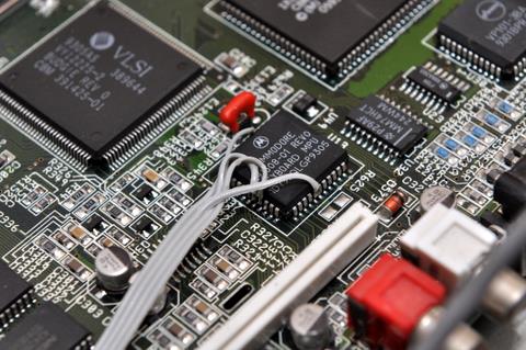
The joystick connector is also used for reading the front panel buttons, so you
can see in that photo that it is passed through a small adaptor circuit first.
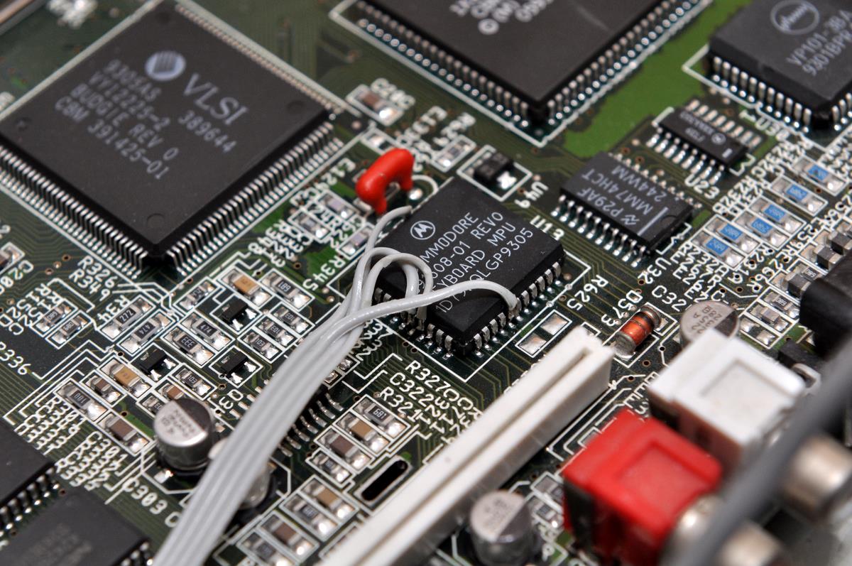
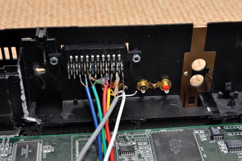
The keyboard socket is wired directly to the keyboard MPU, a hack I already
carried out on my A1200 tower. Many people report having to lift the clock and data legs of the MPU from their pads, but it worked for me both times without that.
 Keyboard connections to MPU for Amiga-
style Keyboards Keyboard connections to MPU for Amiga-
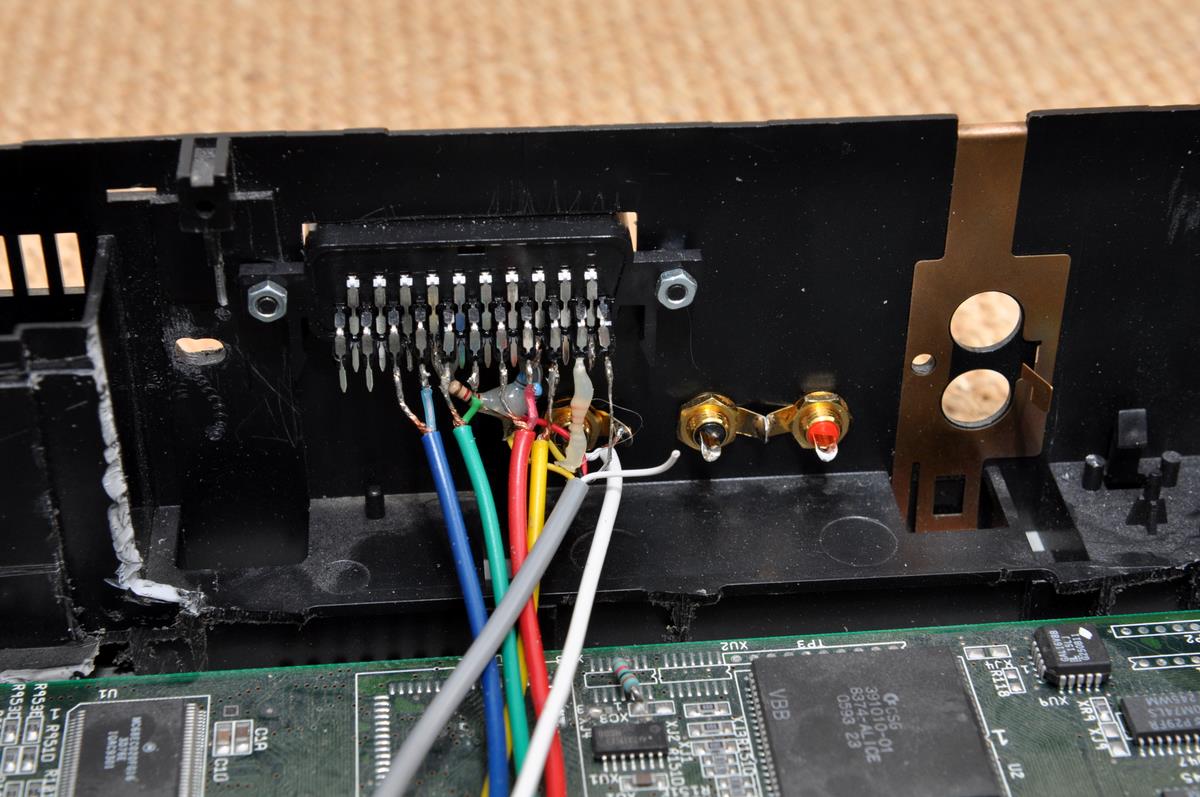
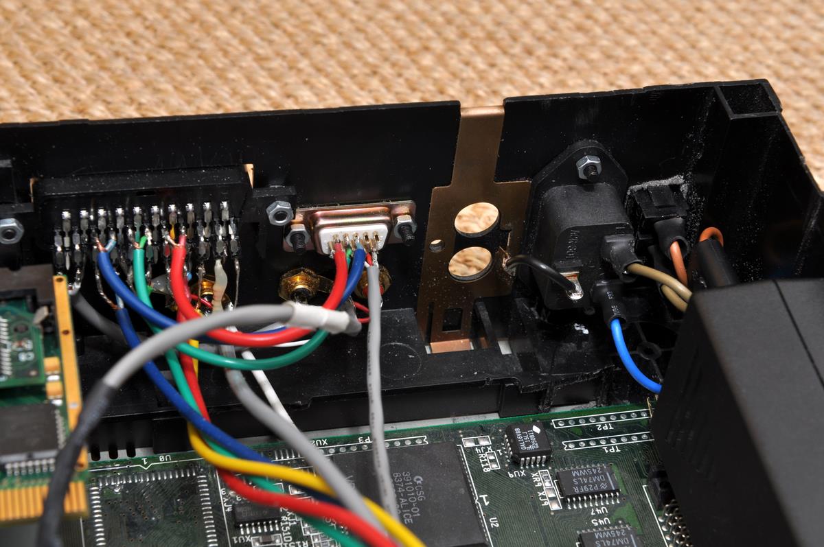
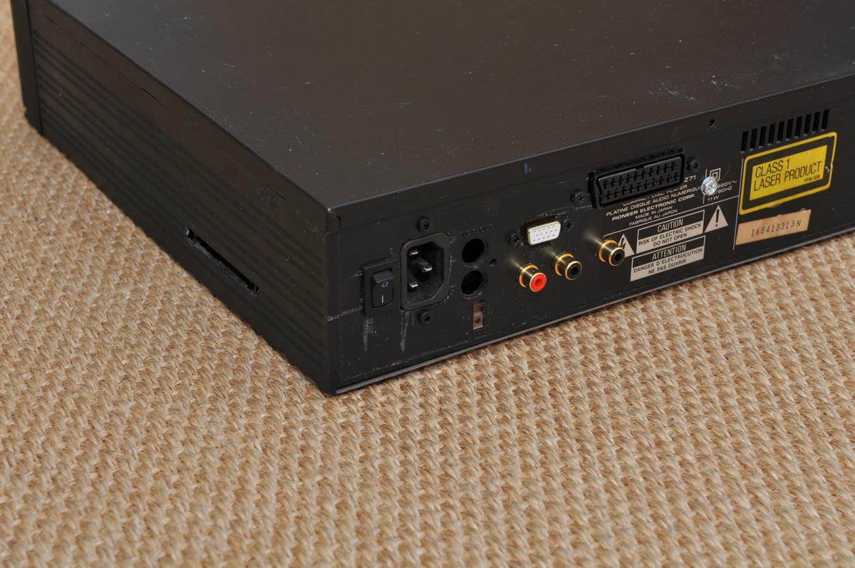
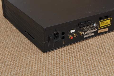
style KeyboardsTo go with the Jukebox's secondary role as a retro games machine that doesn't require having an old beige wedge case lying around the living room, I've added SCART (for RGB) and composite to the rear of the case. The resistors are there to help signals match a modern TV's SCART requirements - if you have one of the original Commodore SCART leads or similar, you might find it won't work with modern TVs, but works fine with the older types. These resistors sort all that
out! The audio connectors aren't connected yet, as I'm still working on the audio mixer circuit...
 SCART, composite and audio connectors at rear of case SCART, composite and audio connectors at rear of case
|

|
|
|
|
| |
|
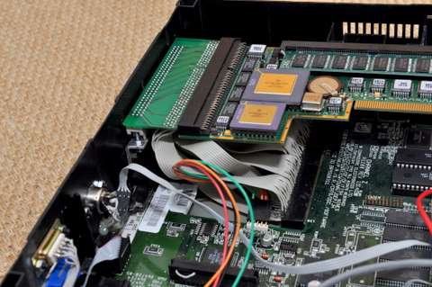
Accelerator CPU Card Relocation
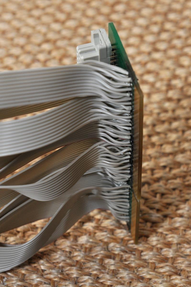
A while ago, it became apparent that the stock 14MHz 68020 wasn't going to be enough for what I wanted to do (running software coded in AmiBlitz BASIC and using ARexx isn't exactly efficient!), so I needed to fit an accelerator. But where? If you look at the case photo, the motherboard itself is a tight squeeze; any accelerator card is a couple of inches too long. So I needed to move it somewhere else. Unable to find any ready-made solution, I set amout making my own. I took a Mediator pass-through connector (since this had both the edge connector and the rare socket required), desoldered the socket from the board and fixed it on the end of a bunch of ribbon cable. Sounds simple, but that connector is 0.05" pitch, double-sided, and totals 150 pins! To mount it on ribbon cable required two layers of cable and involved 4 separate rows of 0.1" connections!! Not one to be deterred by a bit of repetitive work, I got cracking, and this is the result:
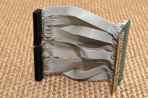 CPU Relocation Bus CPU Relocation Bus
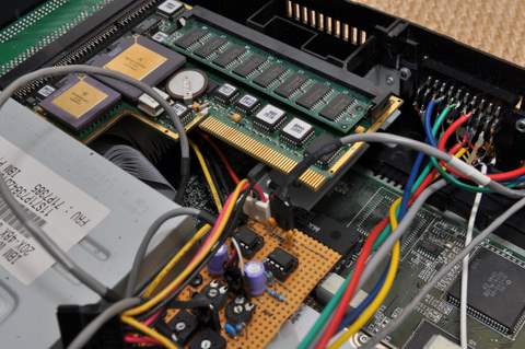
For my fitting, I also had to flip it over, meaning the two layers of ribbon had to be crossed over en route, which you can see in the previous photo. In total, there were 142 connections made at each end - the first 8 pins of the port aren't used. That's 284 connections made in total, each individually stripped, tinned, soldered and checked by hand. I can tell you, I had sore fingers after
all that!!
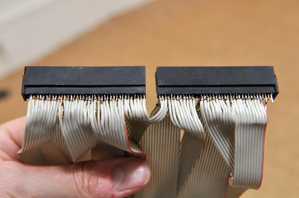
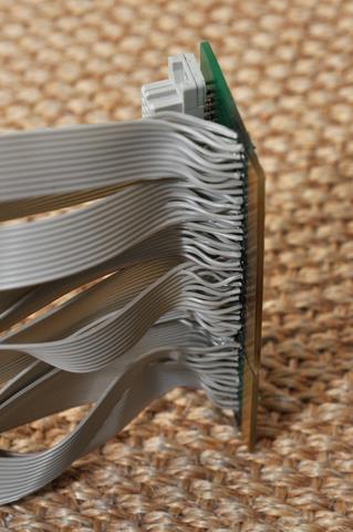 Closer view of the CPU bus Closer view of the CPU busThe plastic connector itself turned out to be made from two separate
connectors carefully spliced together and slightly modified. Presumably Elbox
did this because of the rarity of official connectors, and as a result it became two connectors when separated. Also, it's ever-so-slightly wider than the actual edge connection on the motherboard, meaning some careful moving to get proper alignment. Soldering this connection consisted of two rows of 0.1" pins, and one row of 0.05" connections as this was actually simpler!
 Edge connector socket soldering Edge connector socket soldering
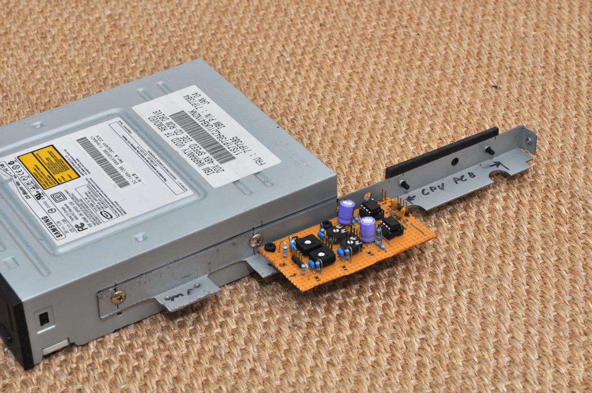
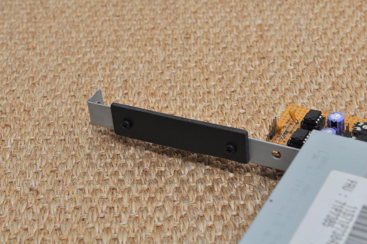
The finished adaptor is fixed in its inverted orientation to the side of the case using small pieces of aluminium made into brackets. They can be seen here:
 Accelerator Board Fitted Accelerator Board Fitted
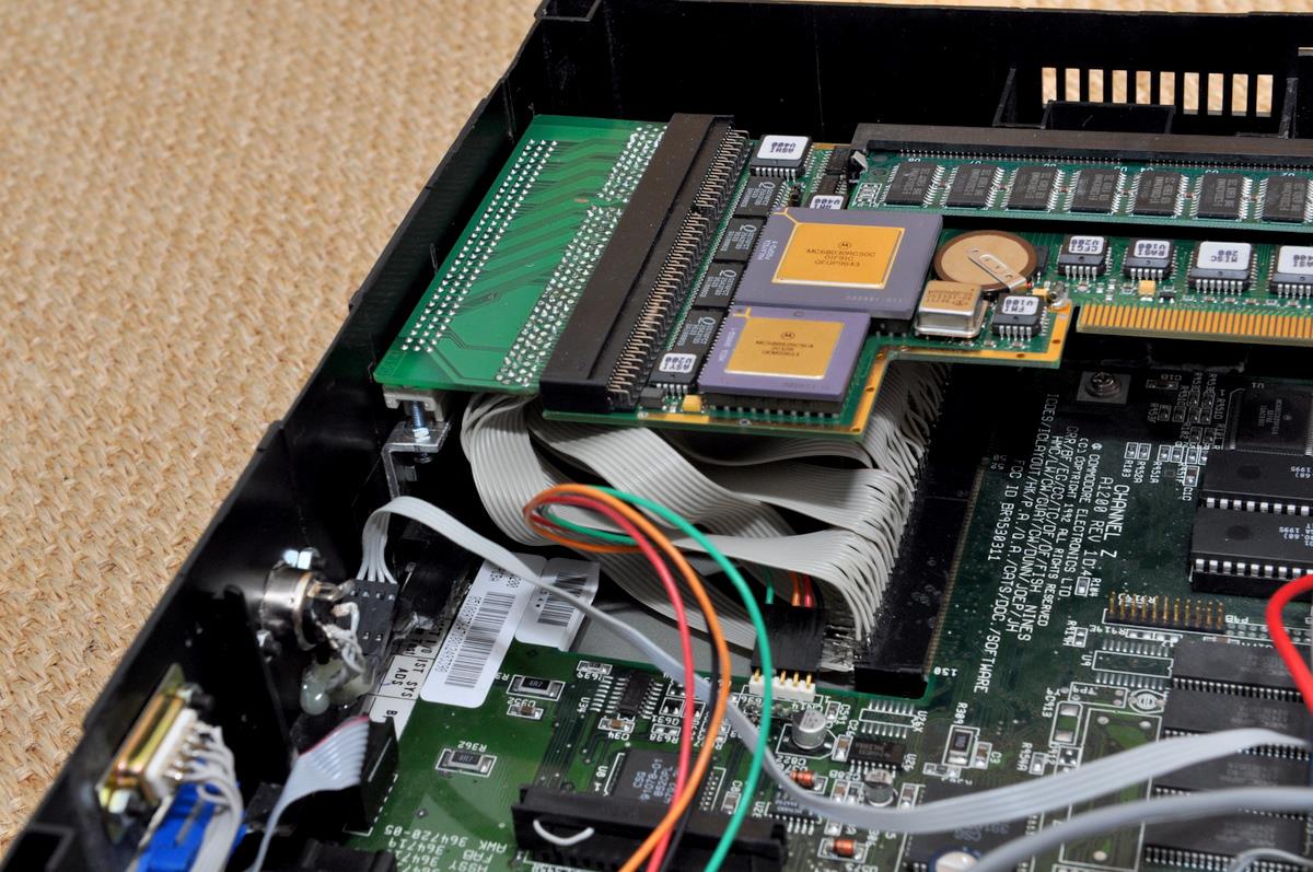
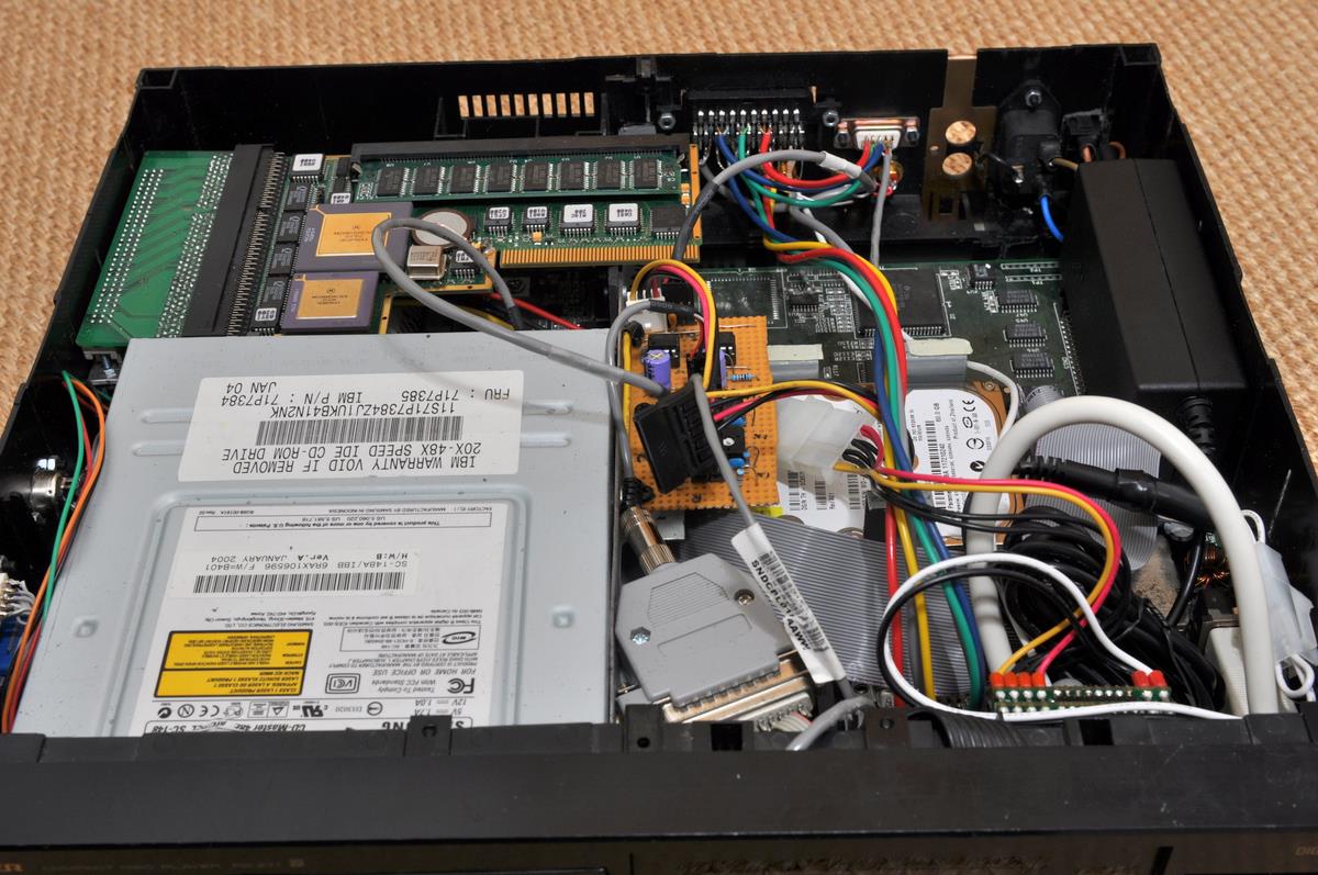
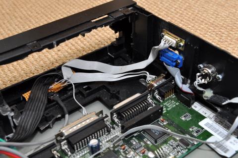
The overall fitting of the accelerator board can be seen in the following photograph. You can also see the hard drive fitted (along with the ribbon cable for CD-ROM drive). The accelerator is fixed in the rear by fitting the edge of the board into a carefully cut slot in the plastic pillar at the back. Seems solid at the moment, but might have to make it a bit more robust - we'll see!
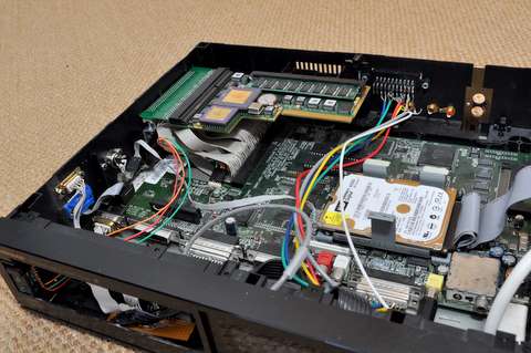 Accelerator Board and Hard Drive Mounted Accelerator Board and Hard Drive Mounted
|
|
|
|
|
| |
|
Front Panel
The front panel worked out incredibly well! Very little work was required to get the Crystalfontz LCD display to fit - it was only slightly bigger than the original display fitted to the CD player. All the existing buttons could be used with appropriate software, though most of the little switches were in a bad way so I replaced them all.
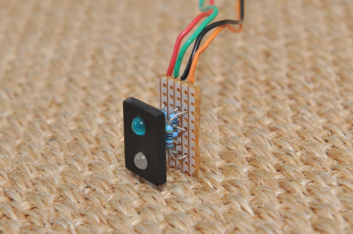
For the power and activity LEDs, I took the original A1200 cable and made a new circuit, with two LEDs mounted in a small block of plastic, just the right size for covering up an ugly hole in the front where the power switch used to be. Blue is for hard drive activity, the tricolour one is green for power, and eventually red might be used for standby.
 Activity and Power LEDs Activity and Power LEDs
|
|
|
|
|
| |
|
|
|
| |
|
The Finished Article
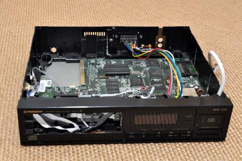
Finally, all the parts fit inside - and more importantly, worked! Although it does look messy in there...
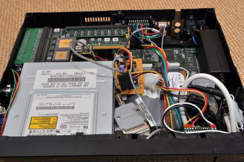 Overview of the internals Overview of the internals
The CPU board fits snugly behind the CD drive and is perfectly supported by the rear of the case and the CD-ROM's bracket. You can also see the end of the bracked held to the back of the case from the outside by a case screw.
 CPU Board Fitted CPU Board Fitted
With all the parts inside, it was tested - and it worked! With that, I fitted the lid of the case - and this is how it looks now:
 The Finished Article The Finished Article
 Keyboard and Mouse/Joystick Ports Keyboard and Mouse/Joystick PortsThe rear ports can be seen here, along with a cutout on the side for the PCMCIA slot. On the back you have the power switch, power connector, VGA port, left and right audio, composite video and SCART. I made a bit of a mess of these cutouts, as you can see from all the nasty saw marks... But hey, they're on the back, so it's okay!
 Rear Ports and PCMCIA Slot Rear Ports and PCMCIA SlotWith everything together and closed up, it was time to try it once again... So I powered it up, and it worked! Not that I didn't expect it to or anything... Here it is, playing a Muse song, and with an Amiga mouse and A3000 keyboard attached.
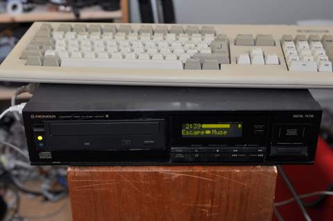 It's Alive!! It's Alive!!
|
|
|
|