This is the Solas Manual, a guide to the installation and usage of the Solas board and its software. This is intended for general usage of Solas; technical details for advanced users and developers can be found here. Click the links below to jump to the section of interest.
Installation is straightforward, but care must be taken as incorrect installation could damage both your Amiga and the Solas board. Solas was designed to be installed directly on the clockport header of the Amiga 1200, but it is also available in a cable-connected version for use in tower conversions or on other Amigas that have clockports fitted.
Installation directly on the A1200 motherboard
The board fits directly onto the clockport header on the motherboard. Great care must be taken to ensure that the connector is correctly aligned, as misaligning the connector can damage your Amiga and your Solas board!
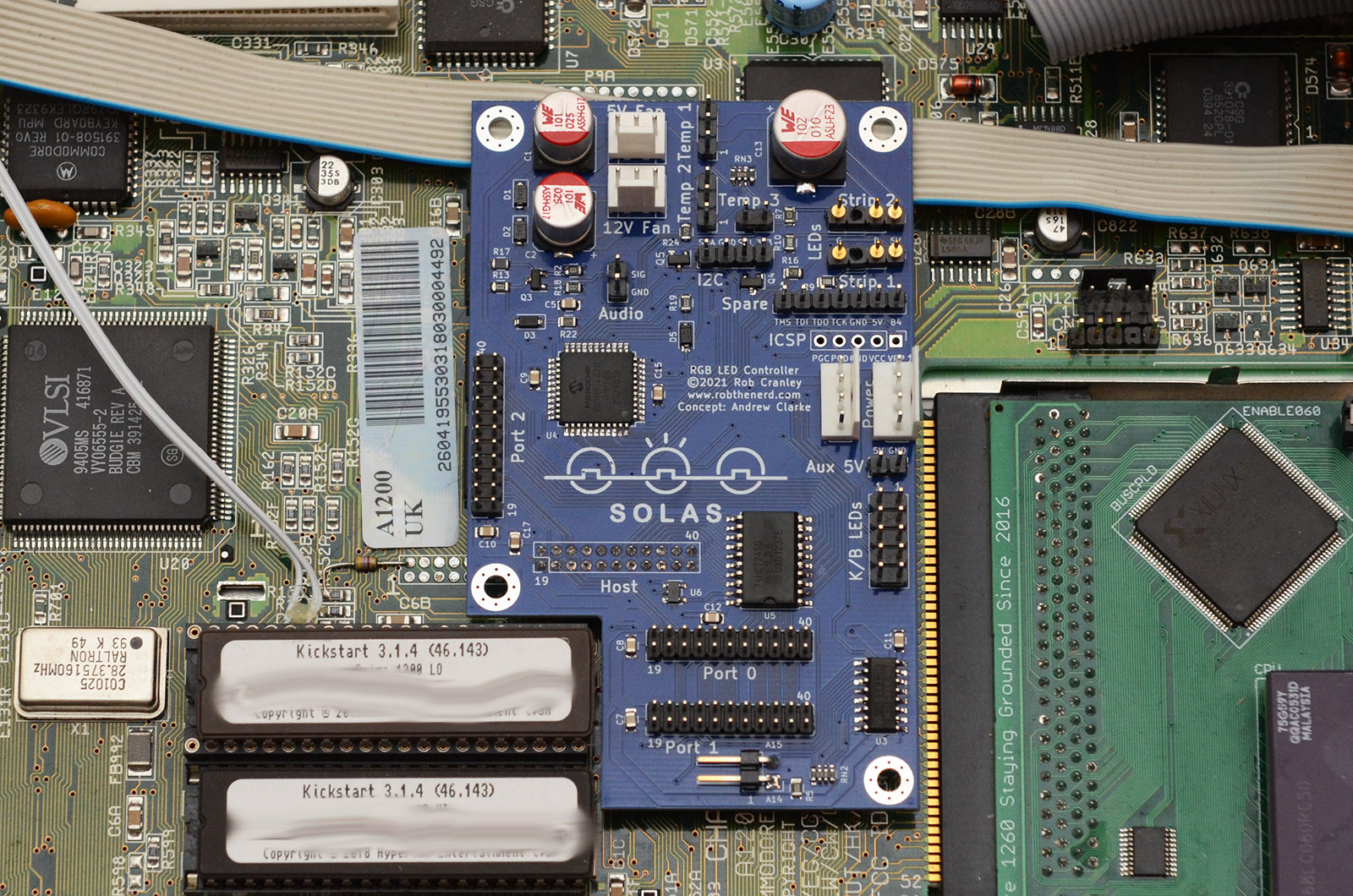
The board should be fitted as shown below - when correctly installed it will be so close to the ROM chips that it could not be fitted and further towards the left or front.
Correct Solas Alignment
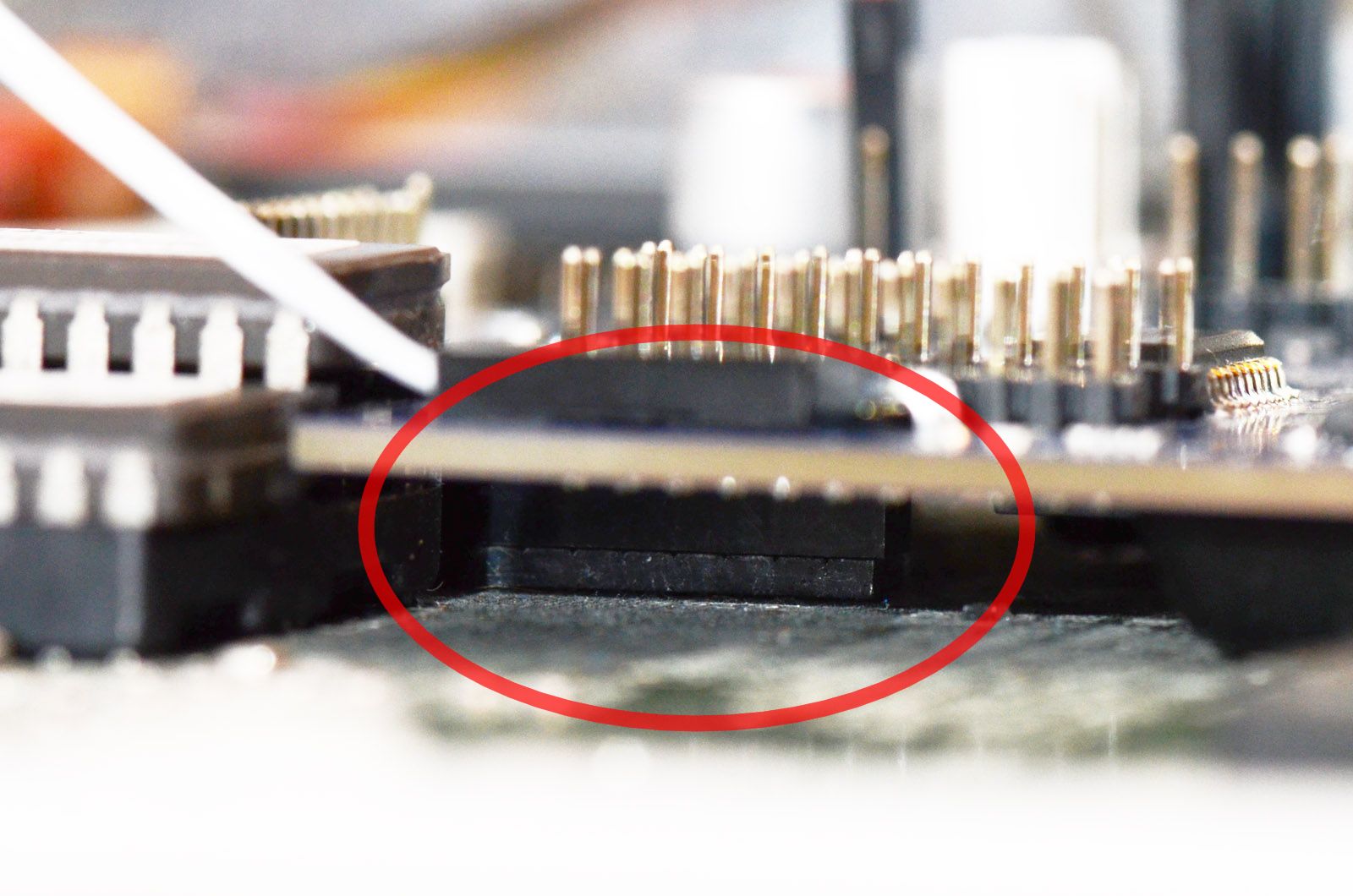
Check carefully from both the front and the left side to ensure that the connector is aligned properly underneath.
Correct Solas Alignment viewed from the front
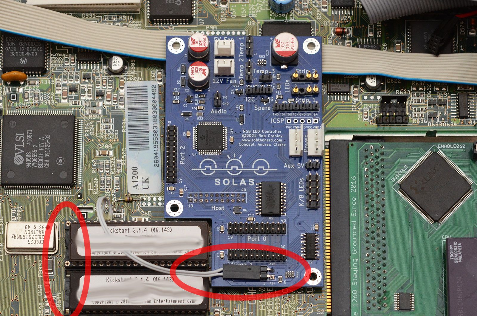
The A14/A15 ROM adaptor fits under either of the ROM chips, and is only needed to activate the clock port splitter functionality. The Solas itself will function fine without it, but the additional clockports will be inactive. To fit this adaptor, remove one of the ROM chips, fit the socket of the adaptor in the ROM socket, and fit the ROM back into the adaptor socket. Note the orientation of the socket, and also note that there are typically two empty pins at the leftmost end. The short cable of the adaptor connects to the Solas as shown below. Note that some additional hardware (e.g. Gayle adaptors) can also offer the A14/A15 connections needed - these can be used instead, avoiding the need for the ROM adaptor.
Address Line Adaptor Fitted
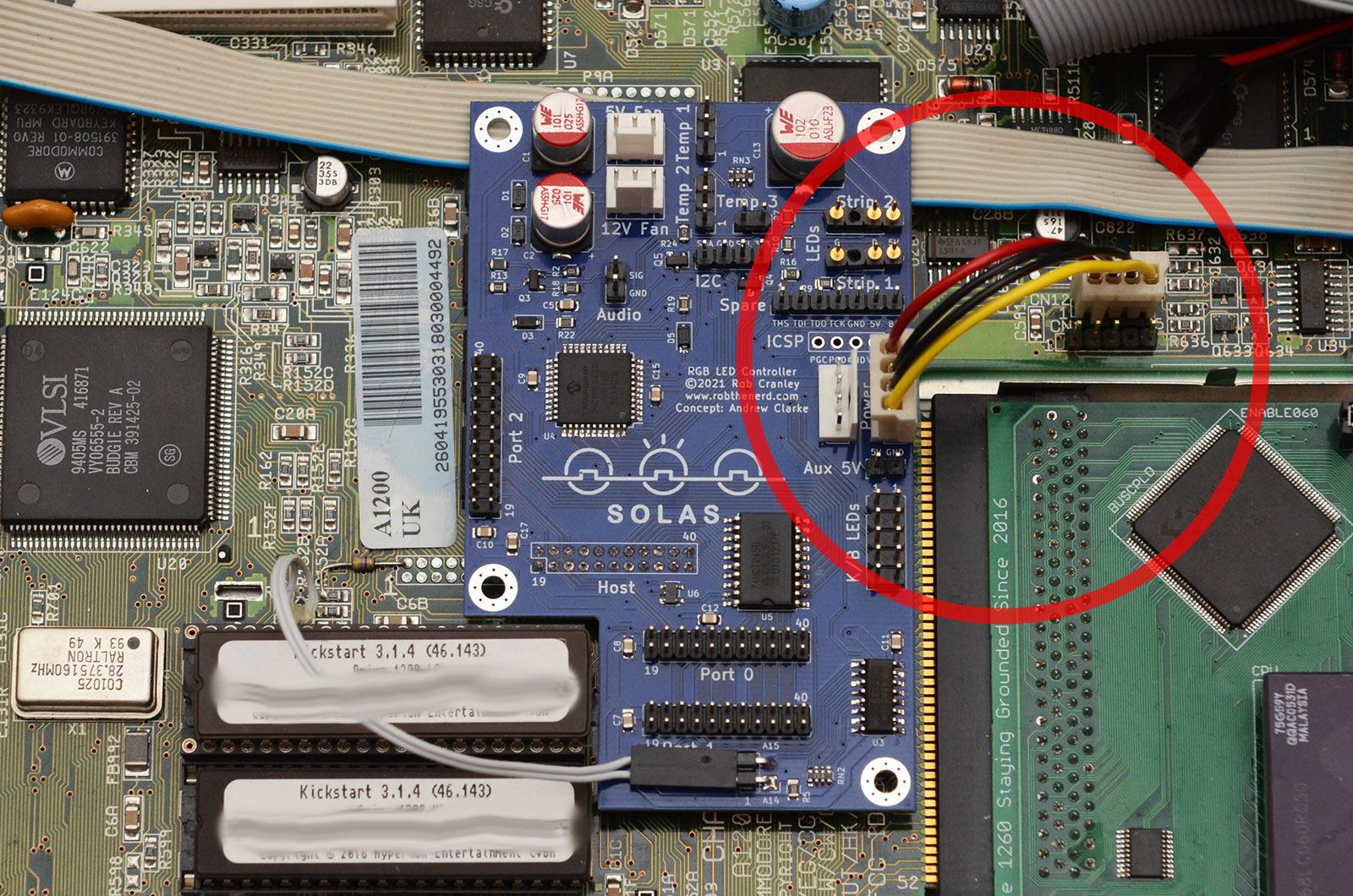
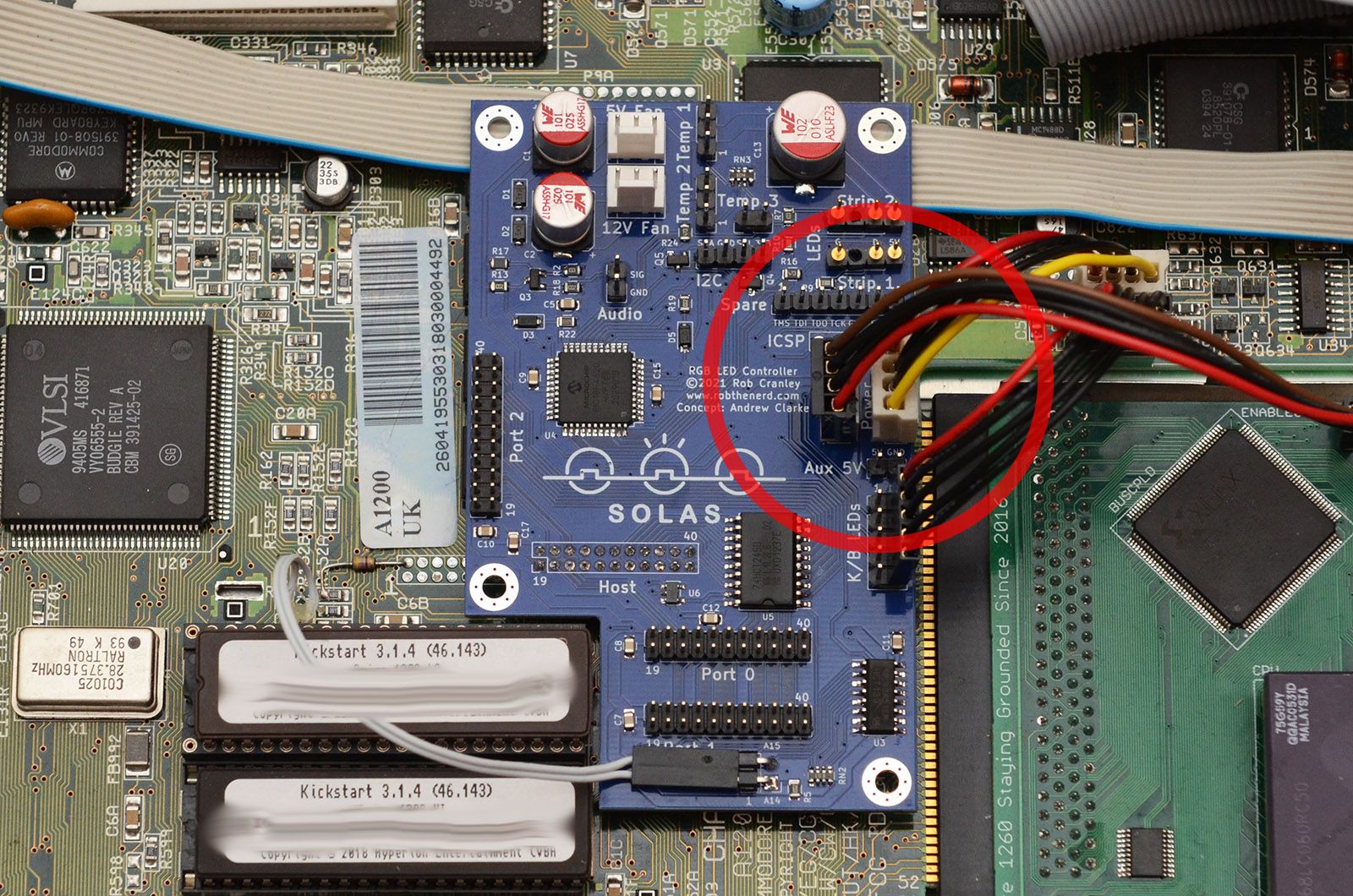
The Solas board requires an additional power connection from the floppy power connector. Use the provided floppy power cable to connect the Solas to the motherboard as shown.
Floppy Power Connection
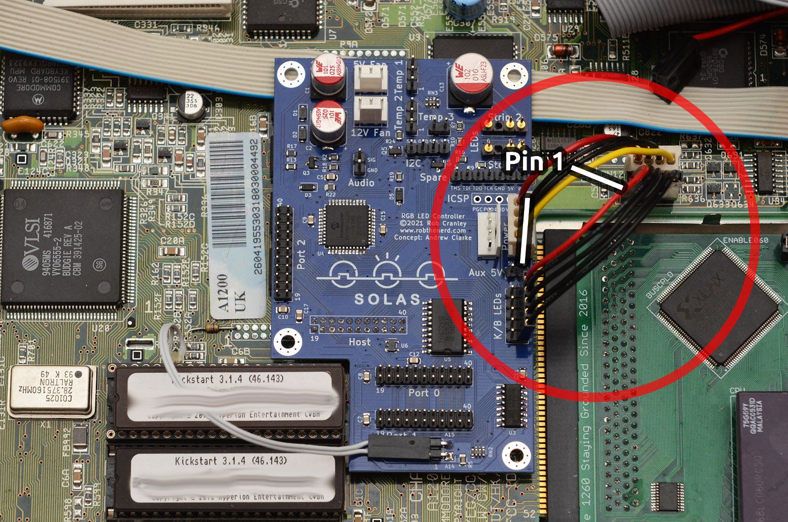
To provide Solas with the drive activity signals, use the provided 5-pin cable to connect the board to the keyboard LED header on the motherboard. Note: Cable orientation is very important! Pin 1 must be connected to pin 1. Pin 1 is located at the left of the motherboard connector, and closest to the floppy power connector on the Solas. For ease of identification, the provided cable has one red wire to indicate pin 1.
This cable is not required if you do not wish to have Solas respond to drive activity with different LED patterns.
Keyboard LED Connection
A passthrough connector is provided to allow connection of the original floppy drive power cable without a Y-splitter. Note that both power connectors have the same function so the cable order doesn't matter.
Floppy Power Passthrough
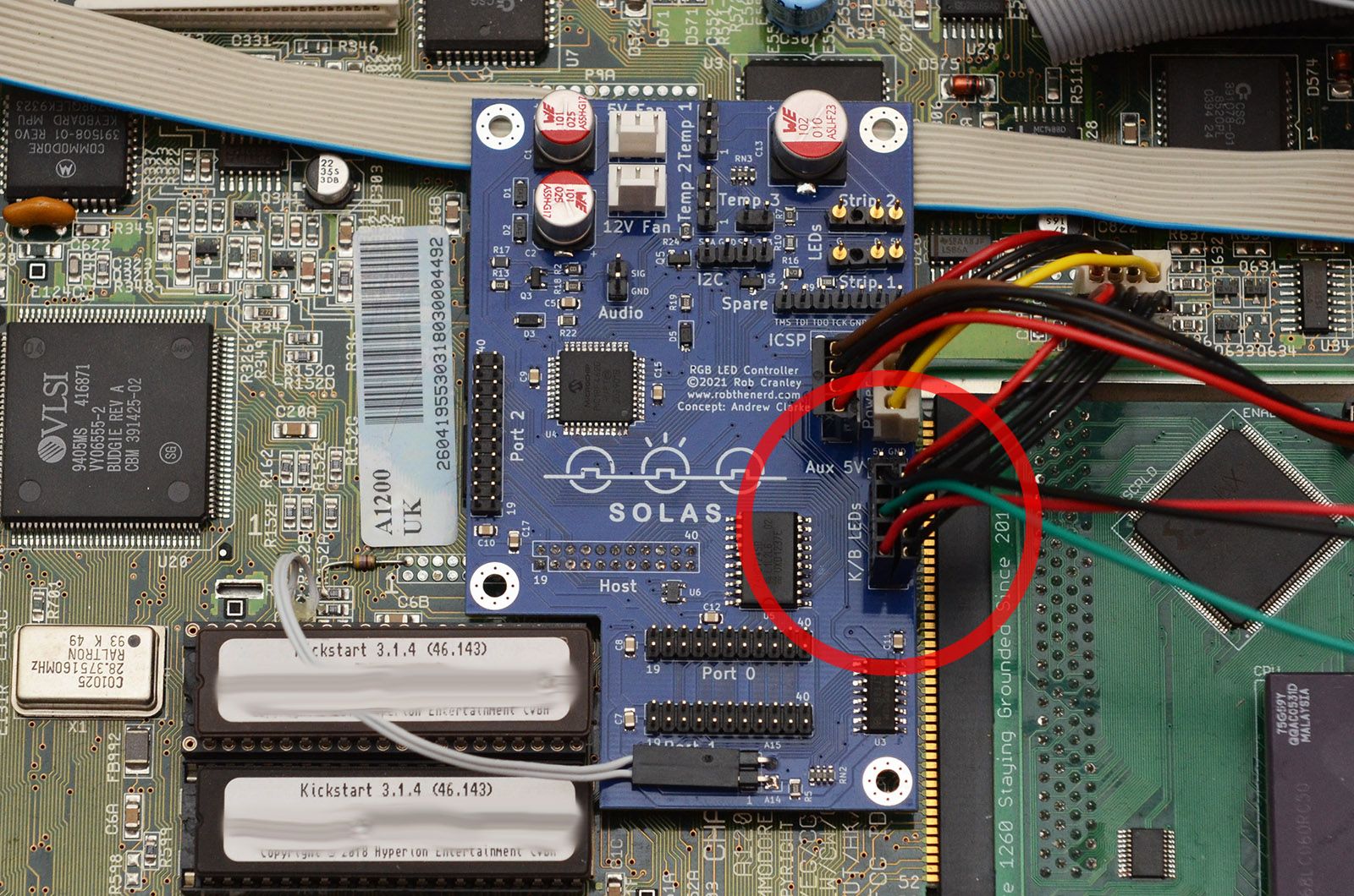
As with the floppy power, a passthrough is provided to allow the connection of the keyboard LEDs without a splitter cable. Note however, that the original LED connector has one pin blocked. This pin was intended for a PCMCIA activity LED that was never implemented, but it's common to modify the A1200 to provide this signal, for example the Bifrost optionally supports this option. If your connector has a blanked pin, a small pin can be used to carefully remove the plug and allow it to be used. Again, pin 1 is located nearest the floppy power connectors.
Keyboard LED Passthrough
Installation Using a Cable
To allow connection to other clockports (e.g. clockports on Zorro cards, accelerators or clockport splitters), or installation on an A1200 setup where mounting directly on the motherboard isn't an option (e.g. towers with Mediator busboards), Solas boards can be fitted with a pin header instead of a socket. A standard 22-pin clockport cable can then be used to connect the Solas "Host" connector to the clockport header. If connected directly to the A1200 motherboard, the clockport splitter function will still be available once the A14/A15 connection is still made (possibly by extension using 0.1" jumper cables). Connecting to any other clockport however, including Zorro clockports and other clockport splitters, will disable the clockport splitter function, so the A14/A15 connection isn't required and Solas will be found at the address determined by the clockport it's connected to.
Add-on Installation
Add-ons for the Solas board provide the inputs and outputs of the various features. They're all optional, and will depend entirely on which features you want to use.
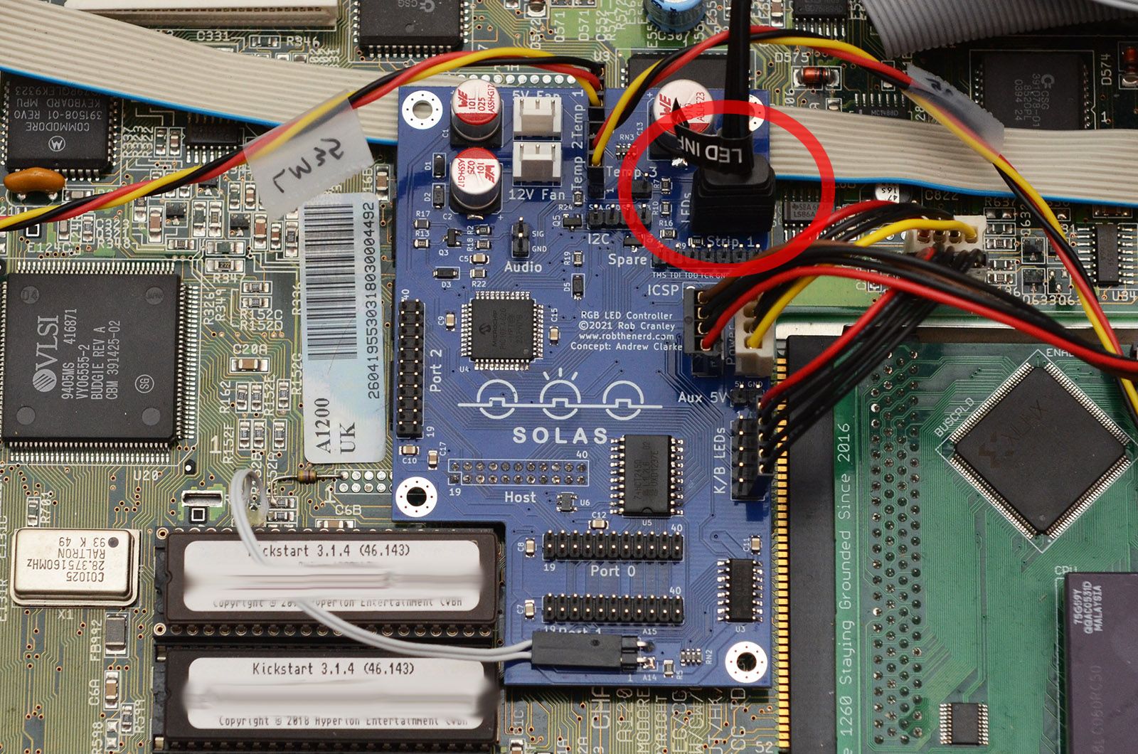
LED Strips
Two LED strip connections are located at the top right of the Solas board. Connect LED strips as desired here, noting that one pin will be blocked on the connector so have a look at the connector to determine the correct orientation.
LED Strip connection
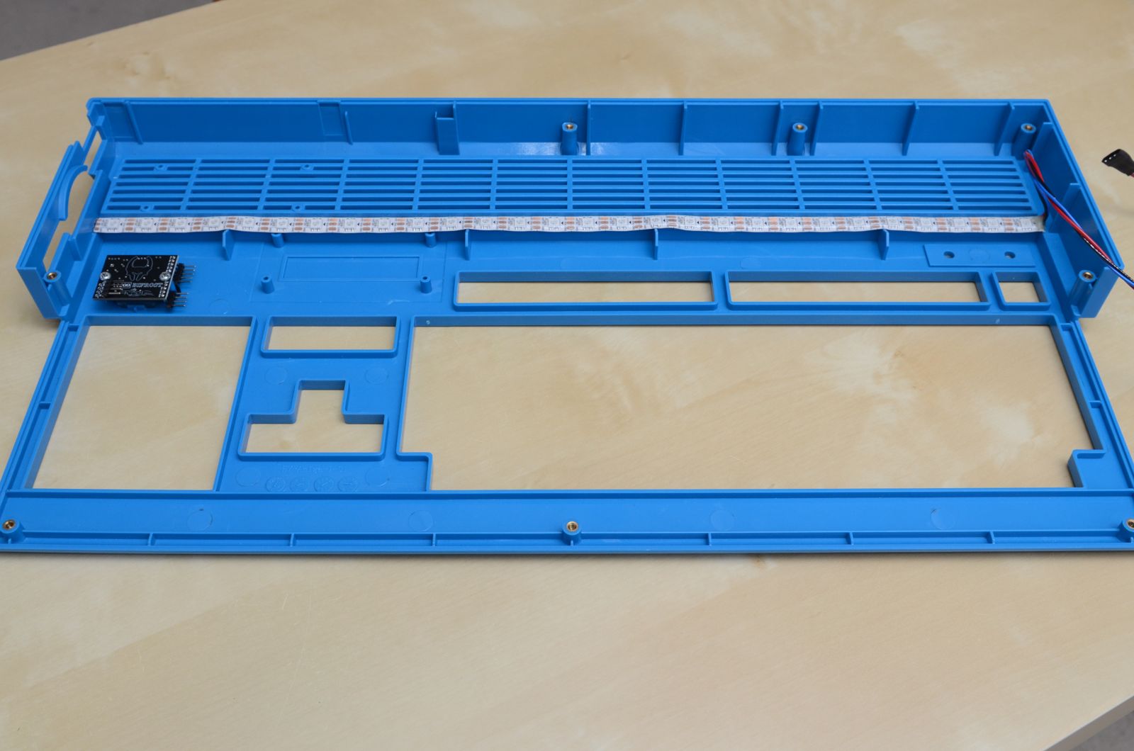
Compatible LED strips are available in a wide variety of shapes and sizes, and how and where they're fitted are entirely up to the user. A basic, self-adhesive LED strip may have been provided with your Solas - this is intended for use on the underside of the A1200 top cover, on an edge just to the front of the vents as shown below.
LED Strip fitting example
These LEDs point down, providing a more diffused glow effect from the reflection of the internals, as direct light from this type of LED is quite intense. Diffused strips are available, as well as other items like fans, heatsinks with compatible LEDs integrated.
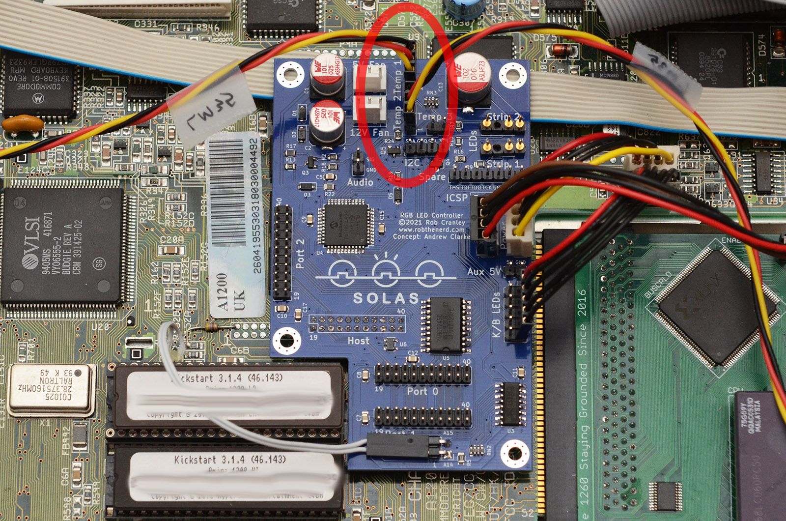
Temperature Sensors
The 3-pin temperature sensor connectors are located at the top of the Solas board. Pin 1 is at the end of the connectors closest to the logo, and is marked on the connector by a small embossed triangle. These sensors are optional, but connect as shown if desired.
Temperature Sensor Connection
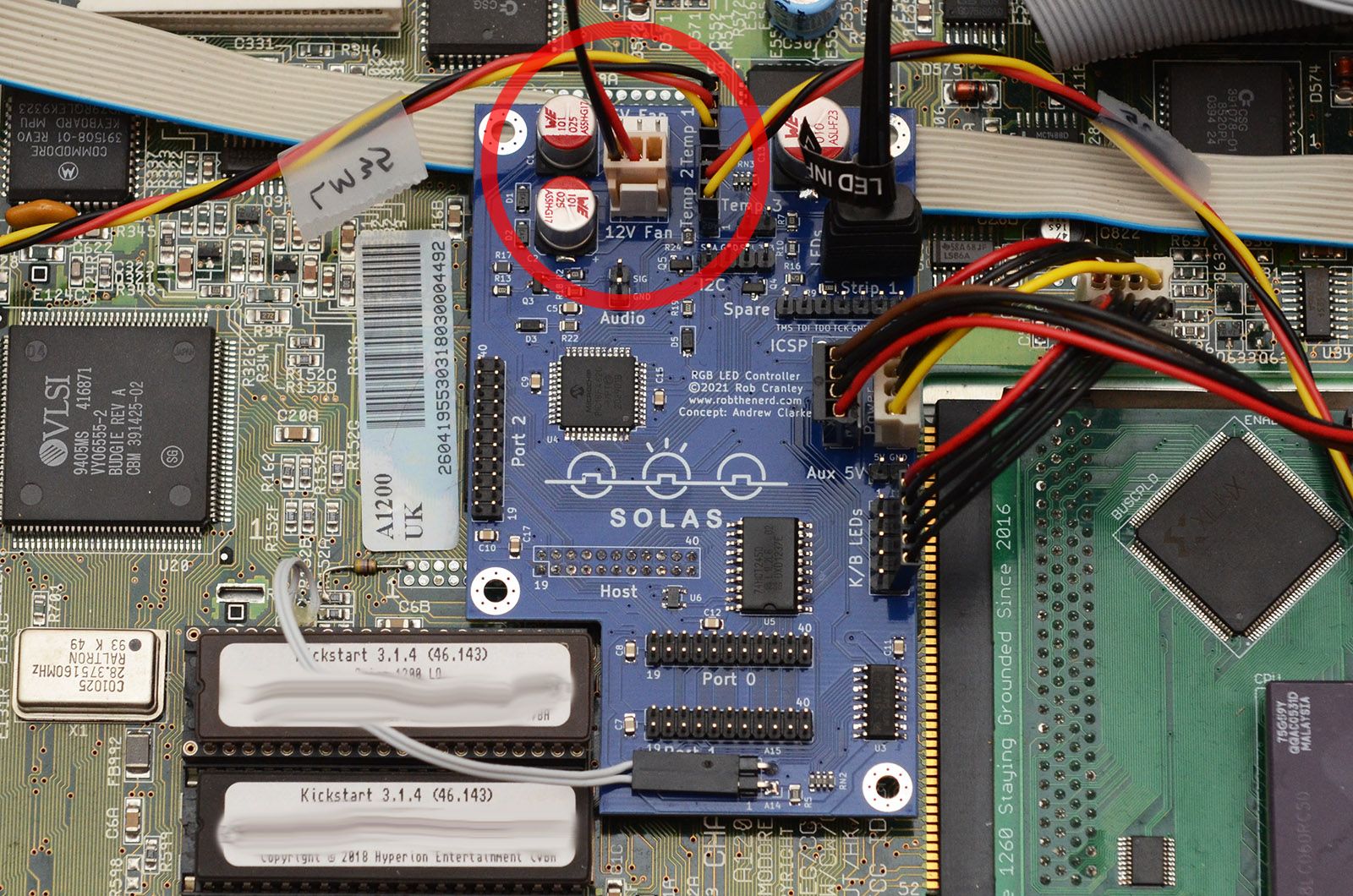
Fans
Two fan connectors are provided at the top of the board - the uppermost is for a 5V fan, the lower connector is for a 12V fan. Standard 2-, 3-, or 4-pin fans can be used, but bear in mind that Solas only controls using a variable voltage, so the additional PWM and tacho functions of 3- and 4-pin fans aren't supported.
Fan connection
Audio Feed
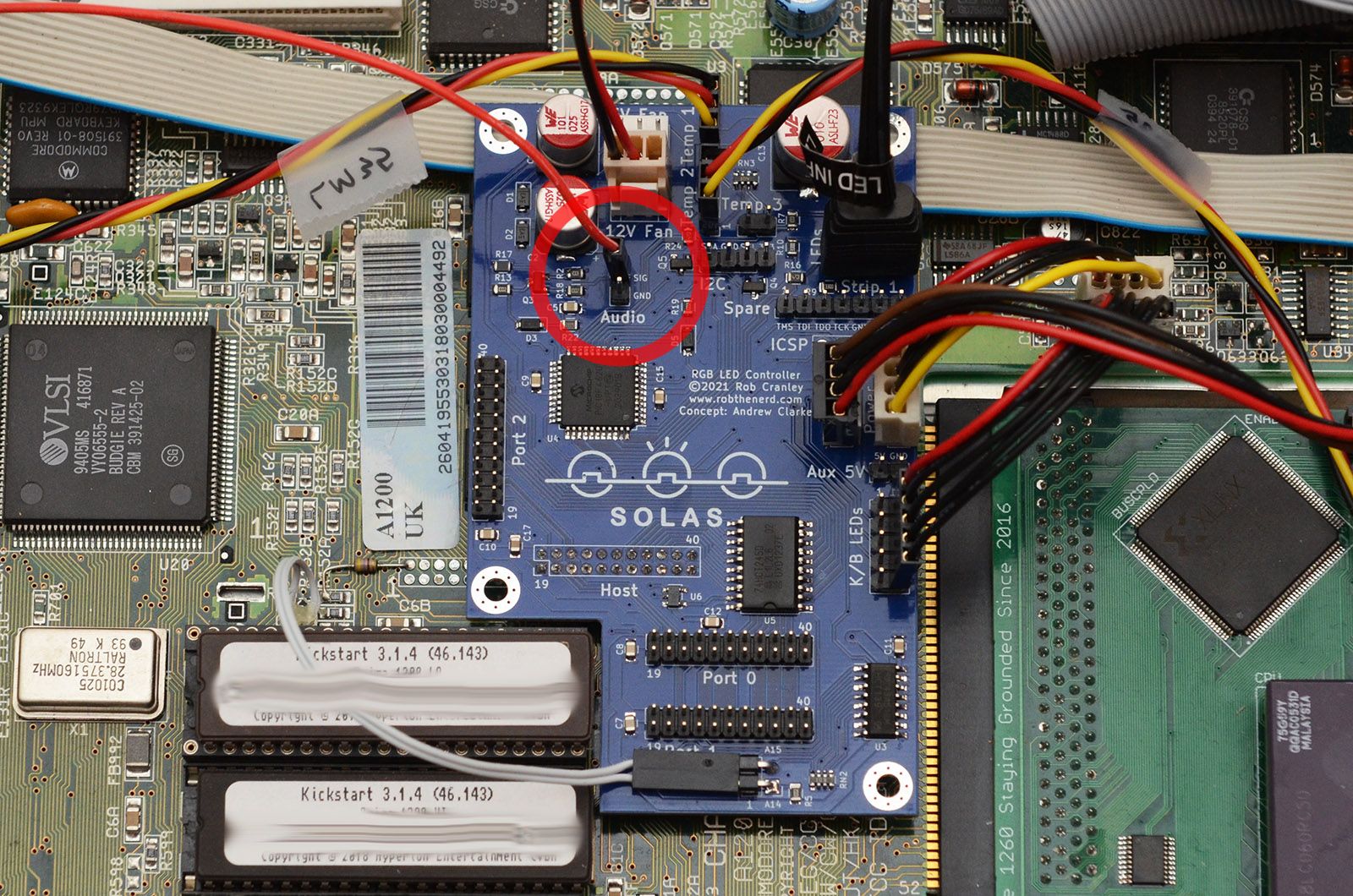
For audio response, Solas can sample a mono audio signal from the Amiga. This signal can be connected to the SIG pin of the Audio header as shown.
Audio Feed Solas Connection
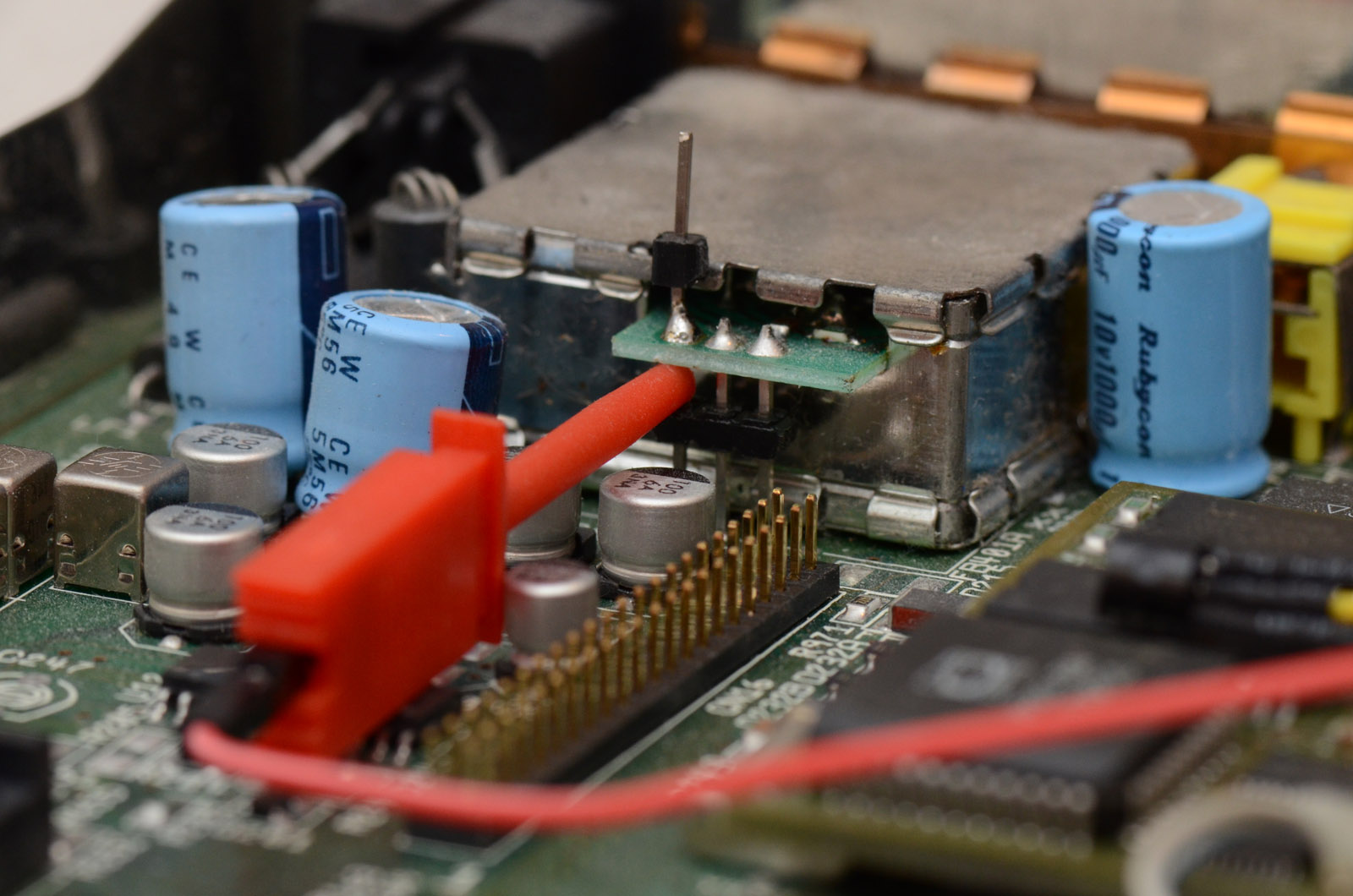
On the A1200 (and A600), the mono audio feed can be obtained from the leftmost pin of the RF modulator. Use the provided clip to attach to the pin as shown. If the modulator has been removed, soldering a pin to the leftmost pad will give you access to the same signal. Consult the A1200 schematics for details (or get someone else to if you're not the soldering type).
Audio Signal From Modulator
Additional Hardware
The Solas board supports an array of additional hardware. So many hardware combinations are available that it's impossible to cover them all here, but hopefully the guidelines below will help you get the most from your Solas board.
Clockport Devices
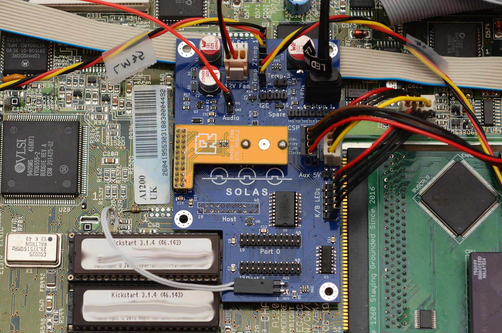
Solas provides an additional three buffered clockports for connecting other clockport peripherals. (It's actually a 4-way splitter, but Solas itself takes up port number 3.) In addition to the non-clock peripherals, support is provided for standard real-time clock modules. Only one may be connected at any time, but Port 2 is positioned to accommodate the commonly available miniature RTC modules that normally fit beside the ROM chips. These can be fitted as shown.
RTC Module Fitment
Other clockport devices can be connected as if connecting to the motherboard. Some devices only work on Port 0 (which is the same address as the motherboard port), but most will work on any port. Cable orientation is very important! This is complicated by the fact that the standard clockport pins don't start at 1 - they're numbered instead from 19 to 40. Further complicating this is that different manufacturers use different conventions for marking orientation - some (e.g. Individual Computers) treat pin 40 as pin 1, others (e.g. E3B) treat pin 19 as pin 1. Solas labels the pins with the same numbers as they are on the motherboard, where pin 40 is closest to the trapdoor expansion connector, and pin 19 is closest to the PCMCIA connector. Always follow the peripheral manufacturer's instructions regarding orientation. If in doubt, pins 19 and 39 are both ground and at opposite ends of the same row, so a multimeter can usually be used to determine the correct alignment. Incorrect connection of clockport peripherals can damage your add-ons, your Solas and your Amiga!
I²C Devices
Solas provides basic I²C host functionality. A 4-pin header towards the top of the board provides the I²C bus connection - it is a 3.3V bus and runs at 100kHz. Pin functions are labelled on the board - be warned that there is no fixed pin arrangement, so pay attention to the pinout of the device you're connecting and arrange the cable as required.
Current I²C support is limited - software is only provided to support commonly found Bosch environmental sensors of the BMP280/BME280 type, and some alphanumeric LCD modules as detailed below. Support for further devices may be added in the future, along with an i2c.library device driver to allow existing I²C software to be used with devices attached to Solas.
LCD Modules Solas supports the use of alphanumeric LCD modules based on a few different controllers, connected to the I²C header. These modules can be used to display temperature information directly from Solas, as well as any other information sent from the Amiga. The table below lists the compatible types, as well as some details on their usage and properties. This may help you decide which module suits your needs.
Midas (RW1063)
Hitachi (HD44780)
Grove (Seeed)
SerLCD (Sparkfun)
Cost (16x2 size)
£12-£15
£4-£5
£7 (monochrome) £14 (RGB)
£17 (monochrome) £22 (RGB)
Availability
Industrial suppliers e.g. Farnell
Very common, e.g. eBay, Amazon
Arduino-type hobby stores, e.g. CoolComponents
Arduino-type hobby stores, e.g. CoolComponents
Backlight
Monochrome
Monochrome
Monochrome or RGB
Monochrome or RGB
Software backlight control
No
On/Off
Brightness / RGB
Brightness / RGB
Software contrast control
No
No
No
Yes
Plug & Play
No (requires soldering to add resistors and connections for contrast and backlight)
Yes (requires backpack board, available pre-assembled)
Yes (requires custom cable)
No (requires header soldered)
Power supply
5V
5V
5V
3.3V (older modules are 5V)
Default I²C address
$7E
$4E
$7C for LCD, $C4 for backlight)
$E4
Footprint
Standard
Standard (extra depth due to backpack)
Non-standard
Standard
Available sizes
8x2 16x2 20x2 20x4 Possibly others...
8x1 8x2 16x2 16x4 20x2 20x4 Possibly others...
16x2
16x2 20x4
Other Notes
Slow communications means more Solas CPU time required
Solas Software
Solas is currently supported by a small suite of programs that can be found on the downloads page. The software can be unpacked and placed wherever is convenient on your system. with the exception of the SolasStyle Shell command, all the programs require MUI to operate.
For any Solas software to be able to find the Solas board, it needs to know its address. Currently, SolasControl will search the standard A1200 clockport addresses ($D80001, $D84001, $D88001 & $D8C001), as well as the /NET_CS address sometimes used by A600 and accelerator clockports ($D90001). If the Solas is connected at another address, for example on a Zorro card clockport, the address must be set manually using the ADDRESS tooltype in the program's icon. (In the future, it may also support automatic detection of Zorro clockports.) Once SolasControl has connected successfully, it will set an environmental variable called "Solas" that contains the address. This is used by the other support programs to easily find the Solas board address.
Solas programs will lock access to the board out while they are communicating, preventing interference from other programs. When this happens, other programs will pause all activity until access to Solas becomes available again. Normally this is only a very short period of time, but SolasControl will block access for the entire time it is running. It may appear that other programs have crashed in this situation, but this probably isn't the case; they'll continue running once SolasControl exits.
SolasControl
This is the main software for controlling most of the features on Solas. It's used for configuring the LED patterns and behaviour, for importing and exporting patterns, for configuring things like temperature sensor calibration, audio sensitivity and fan response curves, as well as updating the Solas firmware. When launched, the main window will open and the program will try to connect to the Solas board.
A status bar at the bottom shows the current status - if the Solas board can't be found, it will say "Not Connected", otherwise it will show the address of the Solas board found. The Live Preview checkbox enables live preview mode, where the current pattern settings are displayed and updated immediately on the LED strip, overriding any other effects in place. Disabling this will return the LED strips to their previous activity. The Apply Current Settings button sends all current settings (all LED, fan and temperature sensor settings) to the Solas board where they will take effect immediately. The Save to Flash button will save the currently active settings on the Solas board to the on-board flash, meaning they will be active from the next reset / power up without having to use SolasControl to set them. Note that Save to Flash will save the current settings on Solas, which might not necessarily match the settings in SolasControl unless they have been applied first.
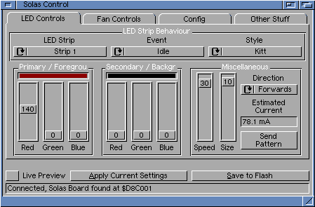
SolasControl LED Controls Tab
The LED Controls Tab allows you to customise the behaviour of the attached LED strips. At the top of the tab, three cycle gadgets choose the overall context of the other controls:
LED Strip selects which LED strip is being customised by the rest of the controls
Event chooses which event the current pattern is applied to:
Idle: Pattern will be active whenever no other events are active
Floppy Access: Pattern will be active whenever the Amiga accesses the internal floppy drive
HDD Access: Pattern will be active whenever the Amiga accesses the internal hard drive (this effect will be triggered for approximately 1 second before returning to the previous event to avoid rapid flickering between patterns)
PCMCIA Access: Pattern will be active whenever the PCMCIA port is accessed. Note that the A1200 requires a modification to the motherboard to enable this feature. As with the HDD activity event, this event will also remain triggered for 1 second before returning to the previous event.
Audio: Pattern will be active whenever the peak audio level is above the required detection threshold. This event will take priority over all other events.
Style selects the pattern that will be applied to the selected LED strip during the selected event. A number of preprogrammed patterns are available:
None Does not apply any effect to the LEDs - if a pattern was already displayed it will remain untouched
Kitt Scrolls a block of colour left and right at the selected speed. Size sets the number of LEDs used, the foreground colour will be faded to the background colour along the size chosen.
Star Trek Viewer Like Kitt but starts at the centre and scrolls left and right in symmetry.
Breathing Fades the whole strip between the foreground and background colours at the speed set. Size and direction settings have no effect.
Solid Sets the whole strip to the foreground colour. No other options have any effect.
Static Pattern Sets the colour pattern sent from SolasControl on the LEDs and leaves them in that pattern. None of the options have an effect.
Scrolling Pattern As for Static pattern, but the pattern scrolls in a loop. Direction selects the direction of the scroll.
Rainbow Cycle Fades the whole strip between red, green and blue at the speed specified. The foreground colour sets the maximum level of each of the three colours, and the background colour sets the minimum. Size and direction settings have no effect.
Rainbow Scroll Sets a rainbow pattern on the LEDs and scrolls it at the speed and in the direction specified. The max and min colour levels are set as with Rainbow Cycle. The size setting specifies the distance between the main colour peaks, e.g. a size of 5 means red will fade to green across 5 LEDs.
Waves Similar to Rainbow Scroll, except the pattern only fades between the foreground and background colours set.
Chase A glow of the primary colour scrolls across, followed by a glow of the secondary colour, each leaving a trail of colour behind. Speed sets the scroll speed, size sets the length of the glow effect.
Lightsaber Fills the strip with the primary colour at the speed specified, then remains full. Sparkles of the secondary colour are provided, and Size sets the strength of the flicker effect.
Level Meter Reacts to audio. The LED strip is filled from one side with the foreground colour based on the sampled audio level. The background colour fills the rest of the LED strip. Speed controls the sample rate, so higher means faster response (normally maximum is best). Size controls the decay rate, with 10 being the fastest decay after a peak. Direction selects from which side the strip fills.
Level Pulses Reacts to audio. The strip is filled with the background colour, and fades towards the foreground colour based on the sampled audio level. Speed and Size controls are similar to Level Meter. Direction has no effect.
Level Cycle Reacts to audio. Similar to Level Pulses, but each time the audio threshold setting is exceeded, the colour is cycled one step through a rainbow cycle. Speed sets the sample speed, size sets the distance between the colour peaks, so a higher size means a larger colour change each step. Direction has no effect.
Level Spread Reacts to audio. Similar to Level Meter, but the fill starts at the centre of the strip and fills towards both ends.
Level Meter VU Reacts to audio. Similar to Level Meter, but the fill uses the primary colour for the first 60% of the strip, the secondary colour for the last 20% of the strip, and a mix of the two for the portion between 60% and 80%. This makes it possible to creat a VU-meter-style colour scheme.
Level Spread VU Reacts to audio. Similar to Level Spread, but with the colour patterns of Level Meter VU above.
Full 24-bit RGB colour sliders are provided for adjusting the main foreground colour of the pattern and the secondary background colour. Small preview areas are provided to give a rough idea of the colour that's set, but bear in mind that the colour produced by RGB LEDs will often differ significantly to a colour shown on a display. See the descriptions of the individual styles for a description of the effects of the colour, speed and Size sliders and the direction cycle gadget.
Using the Settings->Colour Model pull-down menu, the colour sliders can be changed from RGB to HSL or HSV colour representation. This may be preferable for some users as it allows adjustment of saturation and brightness/lightness without having to adjust the RGB values separately. Note however that the colours are always stored and transmitted internally as RGB values, so some conversion and rounding errors will occur when swapping between colour models.
An estimate of the peak current required from the 5V rail of the power supply to display the chosen pattern is displayed at the right of the tab. This can be used to give a rough idea of how much of a load the LEDs will put on the Amiga's PSU. Please note that this is not a real-time measurement of the actual LED strip. This is just a prediction based on measurements taken of a couple of LED strips, extrapolated to take the selected settings into account. The actual current required will vary depending on the exact LED strip used.
Send Pattern allows you to send an IFF palette file to Solas, which will then store the pattern of colours for use in the static and scrolling pattern styles. This file can be created in a paint program, or palette editor such as PaletteEd. Any number of colours can be used - if the LED strip has more LEDs than colours in the palette, the extra LEDs will be left blank. Colours beyond the number of LEDs in the strip will not be displayed.
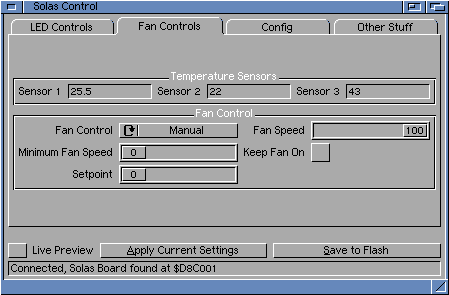
SolasControl Fan Controls Tab
The Fan Controls tab displays the readings from the three temperature sensors, and allows control of the fan speed. All temperatures are in degrees C. The options on this tab allow detailed control over the fan behaviour.
Fan Control selects how the fan speed is controlled:
Manual The fan speed is set by the Fan Speed slider
Sensor 1/2/3 The fan speed is controlled automatically to keep the selected sensor reading at or below the temperature on the Setpoint slider
Highest The fan speed is controlled automatically, based on whichever sensor is reading the highest temperature
Fan Speed Sets the speed for the fan when in manual mode
Minimum Fan Speed Sets the minimum speed at which the fan should be run. Different fans will have different minimum speeds, and some might vibrate or make noise below a certain speed so this can be set to ensure the fan is kept out of this speed region. A setting around 25-40 is probably suitable for many fans. Note that 5V fans will typically have a higher minimum speed than 12V fans.
Keep Fan On Chooses whether to keep the fan on or not when the speed is below the selected minimum speed. If this is enabled, the fan will stay running at the set minimum speed, even when a lower speed is chosen (either automatically or manually). If this option is disabled, the fan will be turned off completely when the chosen speed is lower than the minimum.
Setpoint Sets the temperature used as a target for automatic fan control.
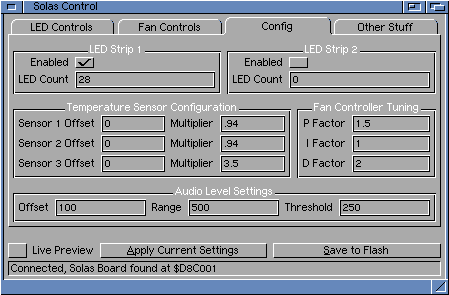
SolasControl Config Window
The Config window allows adjusting of the setup of the board. Typically these settings wouldn't be used much; once they're adjusted as required, they can be saved to the flash of the Solas and left alone. The various configuration options are distributed across a number of tabs based on their function.
LEDs & Audio tab:
LED Strip 1 & LED Strip 2 configuration options tell Solas which LED strips are connected and how long they are. Up to 100 LEDs are supported per strip, though response times and speed of effects may be effected when using very long strips. No harm will be caused by setting them incorrectly, but it's recommended to leave strips disabled if they're not connected so speeds aren't affected. If the LED Count is set higher than the actual length of the strip, the effects will simply disappear off the end of the strip.
Audio Level Settings allow fine-tuning of the audio response. Offset sets the baseline level of the audio, so if you have a response from the Level Meter pattern when no audio is playing, increase this value. Range is the scale of the response, or how much of the audio response is represented by the full strip, so if you have a response that is too small, decrease this value. If even a low sound maxes out the LED response, increase this value. Threshold is the value within the Range that the level must exceed to count as a "beat" and cycle the colour in the Level Cycle LED pattern.
Sensors & Fan tab:
Temperature Sensor Configuration allows the calibration of each of the three sensor inputs. Sensor inputs 1 and 2 are intended for LM3x type sensors, which have a nice linear response. LM35 sensors use an offset value of 0, LM36 use an offset of 78 (or -50). Both types use a multiplier of 1. Sensor 3 is intended for a thermistor, and an offset of 91 with a multiplier of 2.91 is approximately correct for the internal thermistor of a Rev. 4 060 CPU. However, other thermistors (including different revision 060 CPUs) will have significantly different responses; some experimentation will be required to find suitable values.
Fan Controller Tuning allows advanced control of how the fan speed controller reacts to temperatures in automatic modes. The P, I and D values are used to fine-tune the calculations used to determine the fan speed with the aim of minimising annoying fan noise, changes of speed and switching to and from full speed. Since every system and every fan is different, the provided values of 1.5, 1 and 2 are a good starting point, but the ideal values for your system may require some experimentation. PID control is a classic system of control used in all aspects of engineering for generations. The full details of the system can be read about in many places so won't be covered here, but the basics are this: P is for Proportional, and represents how much the fan's response is governed directly by the temperature, i.e. the higher above the setpoint, the faster the fan. Increasing this value will increase the fan speed and response speed, but will also increase "hunting" and overshooting. I is for Integral, and represents how much of the fan's response is based on its previous effectiveness, i.e., the longer the temperature is above the setpoint and the further above it has been, the faster the fan. Increasing this value also increases the response speed and helps to get to the setpoint, but can also introduce hunting. D is for Derivative, and represents how well the system is reacting to the current situation over time, i.e. the error rate. Increasing this value will dampen any oscillations from the P and I functions, but will slow the response somewhat.
Board tab: This contains covers some general functions of Solas.
Reset with host tells Solas whether to reset with the host Amiga or not. If this setting is enabled, Solas will reset whenever the Amiga resets. If it's disabled, Solas will not reset with the Amiga, carrying on as if nothing happened.
HDD/CC0 Event hold tells Solas to extend any HDD, CC0 or audio events by the specified time. This avoids rapid pattern switching caused by quick HDD accesses.
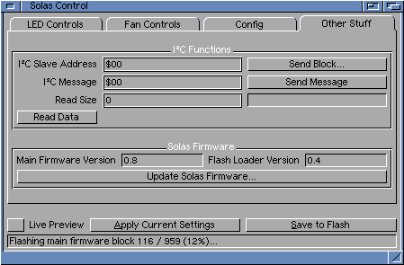
Solas Firmware gives version detail for the main firmware and the flash version, and can be used for updating the Solas firmware.
LCD tab: This contains configuration options for an LCD module attached to Solas via I²C.
Enabled tells Solas to use the LCD module with the given settings. If this option is disabled, no information will be displayed on the module.
Display Type tells Solas the type of display (specifically the control chip) that the attached LCD module uses. Currently there is support for the RW1063 chip (as used in Midas modules) and the ubiquitous Hitachi HD44780 via PCF8574-style backpack.
I²C Address is the address on the I²C bus that the LCD module is using. On Midas modules, the default address is $7E, backpack-equipped Hitachi modules default to $4E, Grove modules default to $7C and Sparkfun modules default to $E4, but it can usually be configured by links or jumpers on most modules to a couple of different addresses, so check the datasheet for your module/interface. Note that this is specified in 8-bit format; if the datasheet gives address in 7-bit format, shift them 1 bit to the left or multiply by 2.
WidthHeight specify how many characters wide and high the display is. Currently up to 40 characters wide and 4 lines high are supported, though only an 8x2 display has been tested so far.
Show Sensor 1 / Sensor 2 / Sensor 3 / Fan Speed tells Solas which (if any) of the internal temperature sensors and fan speed to display automatically on the LCD. These will be assigned to internal page numbers between 8 and 11 as necessary.
Default Page Time is the default period for displaying pages that don't have an individual value specified. This is also used for the automatically generated temperature pages.
Backlight Enable is used to enable or disable the backlight on supported modules.
Backlight Address is the I²C Address of the RGB backlight on modules with a separate backlight controller. Currently only the Grove module supports this arrangement, and has a default address of $C4.
Backlight Red/Green/Blue sliders set the RGB values for the backlight on supported modules (currently Grove and SparkFun modules are available with supported RGB backlights). These sliders will switch to HSL or HSV colour representation if those colour models are selected. On Grove and SparkFun modules where the backlight is controllable but only a single colour, the first slider (Red) will control the brightness and the other sliders won't have any function.
SolasControl supports a number of tooltypes that can be used to adjust the program behaviour:
ADDRESS
By default, SolasControl searches the commonly used clockport addresses to find a Solas board. If enabled, the ADDRESS tooltype can be used to specify the Solas address, and if enabled, overrides the search process and tries to connect at the given address only. This typically isn't needed, but might be used if SolasControl interferes with other clockport devices, for example, or if the Solas is connected to a clockport on a Zorro board or other location with a non-standard address.
COLOURMODEL
This specifies the default colour model to use for the colour sliders when SolasControl starts up. By default these are set to RGB, but this Tooltype can be used to set them to HSL or HSV instead. The pull down menu in SolasControl can be used to change the colour model on the fly once started.
MAXSLB
This is used to set the maximum value to be used for the saturation, luminance and value/brightness values when the colour sliders are set to HSL or HSV modes. Traditionally, these colour models use values from 0-100 for the saturation, luminance and value/brightness levels, but by default, SolasControl uses a maximum value of 255. This helps minimise conversion errors since the colours are always converted to RGB internally, but this Tooltype can be used to set the maximum value to 100 in line with many graphics packages (or, indeed to any other value). The hue sliders are unaffected by this setting and will always have a maximum of 359 in these modes.
SKIPBOARDSEARCH
Tells SolasControl to assume the Solas is connected at the address specified with the ADDRESS Tooltype, or $D8C001 if no address is set. This option can be used to solve problematic board detection when used with accelerators with very tight timing (e.g. ACA1221, TF1260).
SolasHost
SolasHost is a commodity that runs in the background and gives access to the functions of the Solas board via ARexx. It doesn't have an interface and can be quit by running it again, using Exchange to remove it, or sending the QUIT ARexx command to the SOLAS ARexx port.
SolasHost supports the following tooltypes for configuration:
DONOTWAIT
Tells Workbench not to wait for SolasHost to quit when it's started. This is a standard commodity tooltype and is needed if you start SolasHost from WBStartup.
SHOWTIME
If this tooltype is present, SolasHost will use LCD page 0 to display date and time information, regularly updating it when required. Please note that this function won't work when the OS is suspended, e.g. when playing games. As a result, the time displayed on the LCD will remain fixed until the OS is restored.
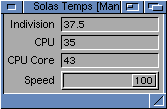
SolasTemps
SolasTemps is a small commodity that reads the temperature sensors attached to Solas, as well as allowing control of the fan speed. As a commodity, it follows the standard commodity conventions, allowing it to be hidden and disabled or enabled by Exchange, start hidden and popping up with a hotkey or by running it twice. In addition, it offers alarm limits, and will warn you whenever any of the temperature sensors reach a configurable limit.
SolasTemps Main Window
SolasTemps is configured using its icon tooltypes. These can be modified using the standard Workbench Icon Information function. Supported tooltypes are:
DONOTWAIT
This tells Workbench not to wait for SolasTemps to finish when it's started from WBStartup. If you don't have this tooltype, starting SolasTemps from WBStartup will give you a warning.
CX_POPUP
This tells SolasTemps whether to open its window when it starts. If set to NO, it will run in the background and remain hidden until called with Exchange, its hotkey or by running it again. Defaults to YES.
CX_POPKEY
This tells Workbench to assign the specified hotkey for opening the SolasTemps window. Defaults to Ctrl+Alt+T.
ADDRESS
This tells SolasTemps the address of the Solas board, since it won't search for itself. Typically, the address will be set by SolasControl and saved as an env variable, but this tooltype can be used to override that setting.
INTERVAL
This tells SolasTemps how quickly it should refresh the data from the sensors. The value is in 1/25ths of a second, so a value of 50 will refresh every 2 seconds, and a value of 250 will refresh every 10 seconds. Defaults to 25, which is every second.
SENSOR1NAME / SENSOR2NAME / SENSOR3NAME
These tell SolasTemps the name to use for displaying the temperature of sensors 1, 2 and 3. Defaults to "Temp 1", "Temp 2" and "Temp 3".
HIDET1 / HIDET2 / HIDET3
These tell SolasTemps to ignore sensor 1, 2 or 3 and hide the display of the sensor's temperature. Defaults to disabled (i.e., show the reading).
SolasTemps allows the user to select from the various fan control modes by selecting the relevant entry from the program's menus. Manual mode allows the fan's speed to be directly controlled using the slider in the SolasTemps main window. A sensor can be selected, in which case the fan's speed will be adjusted to try and maintain the temperature setpoint chosen. The "Highest" mode is similar to the sensor modes but bases the fan speed on whichever temperature reading is the highest.
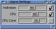
SolasTemps Alarms Window
SolasTemps allows alarm levels to be set for any of the sensors. If any sensor reaches or exceeds the temperature set for an enabled alarm, a warning requester will open with details. The checkbox to the right of each setting allows the alarms to be individually enabled or disabled. Alarm settings are saved and loaded automatically. Note that the alarms will only be active when the commodity is running, so no warning will be given if a temperature exceeds the threshold while playing a game that shuts down the OS, for example.
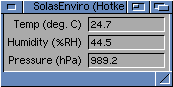
SolasEnviro
SolasEnviro is another commodity that works in a similar way to SolasTemps. However, SolasEnviro reads a BMP/BME280 module that's attached to Solas via the I²C bus. It can read and display the environmental temperature, pressure and humidity as supported by the attached module.
SolasEnviro Main Window
Like SolasTemps, SolasEnviro can be configured using its icon tooltypes. The DONOTWAIT, CX_POPUP, CX_POPKEY, ADDRESS and INTERVAL tooltypes work the same way as for SolasTemps, see above for details on the function of these tooltypes. Other tooltypes specific to SolasEnviro are:
SENSORADDRESS
This tells SolasEnviro the I²C address of the sensor module. Set this to the address of the sensor if it differs from the default location. Note that the unshifted address should be given, i.e., the even/write address. If your sensor documents the address in shifted format (below $7F), shift it one bit to the left (multiplying by 2 will give the same result). Defaults to "$EC", which is $76 in shifted format and the default for BMP/BME280 sensors.
HIDETEMP / HIDEHUMIDITY / HIDEPRESSURE
These tell SolasEnviro to ignore the temperature, humidity or pressure readings and hide their display. Defaults to disabled (i.e., show the reading).
SolasStyle
SolasStyle is a Shell command that applies a previously-saved LED style file to a specified event on the Solas board. This can be used to apply different presets to the LEDs in a script, for example. Suitable style files can be saved by the SolasControl software, and contain details of the pattern type, colours, speed, size and direction.
SolasStyle takes several arguments; the AmigaDOS template is STRIP/N,IDLE/S,FDD/S,HDD/S,CC0/S,PREVIEW/S,ENDPREVIEW/S,SAVETOFLASH/S,STYLEFILE These arguments are as follows:
STRIP
This specifies the LED strip that the style should be applied to. Currently the strips are numbered 0 and 1, for the first and second strips respectively. If omitted, strip 0 is assumed.
IDLE / FDD / HDD / CC0
These switches specify the event for which the style will be activated. If omitted, IDLE is assumed.
PREVIEW
This switch tells Solas to display the specified style in Preview mode, meaning it will be shown regardless of any active events. This will take priority over events until cancelled or replaced with another Preview style.
ENDPREVIEW
This switch tells Solas to end the current Preview mode (if active), and revert to the currently active event. Other arguments are ignored when this switch is used.
SAVETOFLASH
This switch tells Solas to that the specified style should also be saved to flash, so it will remain when the Amiga is reset or powered off.
STYLEFILE
This specifies the file containing the style definition you wish to send to Solas. These files are saved by SolasControl.
SolasLCD
SolasLCD is a Shell command for sending messages to be displayed on an LCD module attached to the Solas board. To better understand how to use the display, the following background information might help. Internally, Solas has 8 pages or slots available for displaying messages, numbered 0 to 7. Each page can be enabled or disabled, and Solas will show each enabled page in order, before returning to the first page again. Each page can also have a time set for how long that page will be displayed; a default period can be set in the SolasControl preferences. Additionally, there are optional, automatically-generated pages that display temperature and fan information. These are allocated as pages 8 to 11, depending on how much information can fit on the screen.
SolasLCD takes several arguments; the AmigaDOS template is GETCONFIG/S,PAGE/K/N,TIME/K/N,ONCE/S,NOW/S,MESSAGE These arguments are as follows:
GETCONFIG
This does not send a message, but instead queries Solas for the current LCD configuration, including details like the dimensions of the display and whether it's currently enabled. Other arguments will be ignored if this switch is used.
PAGE
This value tells Solas the page number to use for the message. If omitted, page 0 will be assumed.
TIME
This value sets how long the message's page will be displayed before Solas moves onto the next displayable page. If omitted (or set to 0), the default time as set in the preferences will be used.
ONCE
This switch tells Solas that the message should only be displayed once. After it has been displayed for the set amount of time, the page the message is in will be disabled. If omitted, the message will be redisplayed each time Solas cycles through all the pages.
NOW
This switch tells Solas to immediately switch to the page of the message, so that it's displayed right away. If omitted, Solas will display the new message when it comes to the message's page as it cycles through the pages.
MESSAGE
This is the string that makes up the message. No formatting is done, so you will need to pad it with spaces to align lines, centre text etc. to suit the display. Text will wrap directly onto the next line of the display, and any characters beyond the size of the display will be ignored. Enclosing the string in quotes will help preserve the space formatting.
Updating Solas Firmware
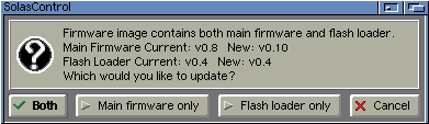
The Solas board firmware can be updated using the "Board" tab in the SolasControl Configuration window. The current version of the detected board is displayed here. There are actually two separate firmware modules - the main one that controls all of Solas' functions, and the flashloader one that is used to update the main firmware. Typically it will just be the main firmware that needs to be updated.
The firmware can be downloaded on the Downloads page. Normally you'll only need the latest version, but older versions may be used for testing purposes or if there are issues with the latest version. The file is provided in an archive and needs to be unpacked before it can be used - the firmware updater uses files in Intel .hex format. Select the required .hex file after clicking the "Update Solas Firmware..." button. A warning will be given to not interrupt the firmware update process. It's a good idea to not run any other software that might interfere or cause a crash while the update is going on - if the firmware update is interrupted, the board will need to be reflashed with a cable.
The .hex file will be processed and the actual flashing process can then begin. The .hex file may contain the main firmware, the flash loader firmware, or both. Some version information will be shown, and you will be given the option of updating either or both of the firmwares if more than one is present. To save time, it's probably best to only update the one that needs to be updated.
Firmware Update Options
The firmware flashing process will take a few minutes; the current progress will be shown in the status bar at the bottom of the window. When the process is complete, the board will reset. It's a good idea at that point to quit SolasControl and restart it to reconnect to the board. Once SolasControl is restarted, it will show the new firmware versions.
Firmware Update in Progress
Solas ARexx Control
Most of the features of Solas can be accessed via ARexx, allowing it to be controlled from any other application with ARexx support, as well as from stand-alone ARexx scripts. The SolasHost commodity presents an ARexx port port called SOLAS, which is used to communicate with the Solas board. Available ARexx commands are detailed below.
Arguments (where required) are separated by a space, so if a text argument is to be passed to the SOLAS ARexx port, it's important to ensure it's fully enclosed in quotes. Single quotes can be used from ARexx scripts so that ARexx ignores the contents of the string and passes it on unaffected. RGB values are always from 0-255. If fewer arguments than required are provided, the missing arguments are assumed to be 0.
QUIT
This tells SolasHost to quit, closing the SOLAS ARexx port.
LEDMODE mode
This sets the current mode for controlling the LED strips. Mode 0 is the default, with Solas applying the patterns and animation defined by the SolasControl settings. Mode 1 ignores all event settings and allows full, manual control of all the LEDs from ARexx using the commands below. The LED commands will be executed in either mode, but if Solas is handling animations, it will overwrite the sent colours whenever it next refreshes.
CURRENTSTRIP strip
This tells Solas which strip should be referenced for any commands that concern the LED functionality. Currently can be 0 for the first LED strip, or 1 for the second LED strip.
ALLOFF
Turns off all LEDs in the current strip by setting all their RGB values to 0, 0, 0.
SETALLLEDS red green blue
Sets all the LEDs in the current strip to the RGB values given.
SETSINGLELED led red green blue
Sets the LED specified by led to the given RGB values. LEDs are numbered starting at 0 for the first LED.
FILLLEDS startled count red green blue
Sets a number of LEDs to the given RGB values. startled specifies the first LED to be set, and count specifies the number of LEDs that should be set, starting from startled.
SENDPATTERN filename
Sends a pattern of up to 100 RGB values to be stored in the pattern slot for the current strip. This is the pattern used by "pattern" LED effect styles when set in SolasControl.
STOREPATTERN
This tells Solas to store the currently displayed pattern of LEDs on the current strip in the pattern slot for the current strip, allowing it to be used later by a "pattern" effect. Note: Not yet implemented.
SAVETOFLASH
This tells Solas to save all the currently active settings to flash, so they will be the default the next time Solas starts up. Note that for the LED strips, this uses the LED mode 0 settings; any applied mode 1 patterns are not stored.
LOADFROMFLASH
This tells Solas to load the settings saved in flash, replacing any active settings.
PREVIEW
This puts Solas in Preview mode, which overrides any active events and applies the event types and settings sent in realtime.
ENDPREVIEW
This cancels Preview mode, returning Solas to the standard event behaviour.
LCDMODE mode
This is similar in concept to the LED mode setting described above. Mode 0 is the default, "paged" mode where Solas rotates through any enabled pages of information it has available and displays them on an attached LCD module. This can include temperature and fan information if enabled in the SolasControl settings, as well as any pages of information sent via the LCDMESSAGE ARexx command or the SolasLCD Shell command. Mode 1 sets Solas to use the LCD in "direct" mode, so no pages of information are shown and instead the displayed content is fully under the control of ARexx using the commands below.
LCDCLEAR
Clears the LCD screen and moves the cursor to position 0, 0 (top left). Only applicable in direct mode.
LCDHOME
Moves the cursor to position 0, 0 (top left) without clearing the contents. Only applicable in direct mode.
LCDLOCATE x y
Moves the cursor to the X, Y position specified. 0, 0 is the top left corner. Only applicable in direct mode.
LCDPRINT string
Prints the given string at the current cursor position. If the string extends beyond the right edge of the screen, it will wrap around to the next line. Only applicable in direct mode.
LCDMESSAGE page time flags line message
Sends a complete page to be added to the page rotation for display on the LCD module. These pages can be send at any time, but will only be displayed when in paged mode. page is the page slot to control, from 0-7. time
LCDBACKLIGHT enabled red green blue
Sets the LCD backlight settings. enabled turns the backlight on or off, with 0 specifying off and 1 specifying on. The colour settings set the RGB values to use for the backlight. Where the backlight supports software control but doesn't have RGB capability, the red value will usually specify the brightness. Note that support varies between LCD modules; see the section on LCD modules above.
LCDCONTRAST contrast
Sets the LCD contrast setting. contrast is the value to use, from 0-255 with 255 being the darkest. Note that support varies between LCD modules; see the section on LCD modules above.
Solas can also be queried for information with the following commands. These will return the results in the RESULT variable. Be sure to include the OPTIONS RESULTS line in your scripts or you won't be able to receive the results. Where more than one value is returned, they will be separated by spaces in the result string. These can be interpreted separately using the WORD() function or similar.
GETLCDSETTINGS
Returns some of the key settings of the LCD module in the format "enabled width height". enabled will be 1 if the LCD module is enabled, 0 otherwise. width and height are the set dimensions of the LCD, useful for planning the layout of messages.
GETTEMP sensor
Returns the current temperature of the specified sensor. Currently, this value is 0, 1 or 2 for the three sensors on Solas.