|
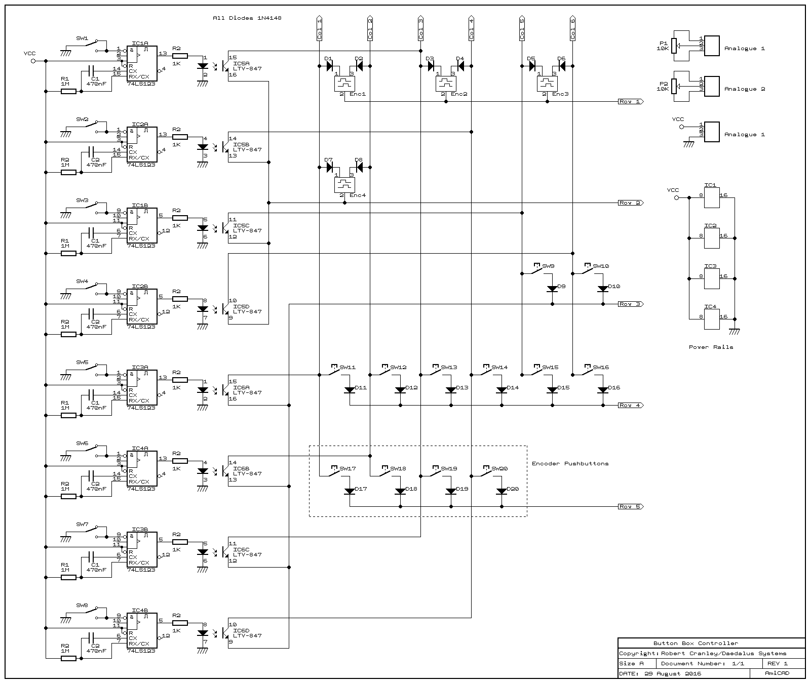
The switch matrix makes things slightly complicated due to how it works. The theory of these layouts is that all columns are kept in the same state, and then each column is pulsed in turn, while the controller software watches for any rows showing a signal. This means that the controller is able to distinguish between different buttons without having a connection to all of them. The main drawback is that multiple switches aren't always recognised at that, so to get around this, a diode is put in series with each switch so that the pulse isn't sent back through the closed switches to confuse the controller. If you're interested in a better explanation of key matrices, check this page out.
Support for multiple button presses is not so important for buttons that are only pressed momentarily, but because I wanted the possibility of having held buttons or switches, I decided to add diodes for all inputs. The other issue was that the toggle switch inputs didn't really translate well to game inputs, most of which expect a momentary input like a key press. I could simply use all pushbuttons, but I liked the idea of toggle switches so I came up with a way of converting toggle switches to momentary signals. To do this, I used a monostable flip-flop for each input to give me a momentary output for each switch action. Wiring both sides of the toggle switch together gives a single pulse for either direction, which works for an input expecting a keypress to toggle, e.g. using the same key to raise or lower the landing gear.
Connecting this logic-level output as an input to the key matrix is tricky however, since it doesn't match the pulses used. To bridge this difference, I used optical isolators, which also have the benefit of not requiring the diode since they are based on a transistor. I just had to connect them the right way around...
|

|


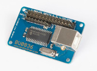 The interface board I selected is the rather excellent